Plasma etching machine

An etching machine and plasma technology, applied in discharge tubes, electrical components, circuits, etc., can solve problems such as increased plasma energy, frequent alarms from alarm equipment, and easy entry of plasma, so as to avoid insulation failure and abnormalities Discharge, the effect of good market prospects

Active Publication Date: 2016-01-06
BOE TECH GRP CO LTD +1
View PDF3 Cites 9 Cited by
  • Summary
  • Abstract
  • Description
  • Claims
  • Application Information

AI Technical Summary

Problems solved by technology

[0004] First of all, the ceramic sheet 4 has been under the condition of plasma bombardment, and its diameter and thickness are continuously lost, so that the plasma easily enters the installation hole and damages the ion generating electrode 2; secondly, the newly developed etching process makes the plasma have the energy increase, the wear speed of the ceramic sheet 4 becomes faster, and the damage degree of the plasma to the ion generating electrode 2 is also more serious; finally, the mounting screw 3 is prone to fragmentation when thermal expansion and contraction occur, thereby causing the support frame 1 to contact with the ion The connection of electrode 2 is not firm
[0005] The reason why the plasma can damage the ion generating electrode 2 is because the ion generating electrode 2 is made of metal material, and the plasma can melt the metal material. When the plasma enters the threaded hole of the ion generating electrode 2, it will destroy the threaded hole and cause ion The insulation failure of the generation electrode 2 makes it unusable, and the abnormal discharge of the ion generation electrode 2 causes frequent alarms from the alarm equipment

Method used


Image

  • Plasma etching machine
  • Plasma etching machine
  • Plasma etching machine

Examples


Embodiment 1

[0027] This embodiment provides a plasma etching machine. The plasma etching machine includes a sealing cap and a sealing unit, which can effectively block the plasma above the support frame from entering the threaded hole of the ion generating electrode for a long time, so as to avoid plasma damage to the thread. hole.

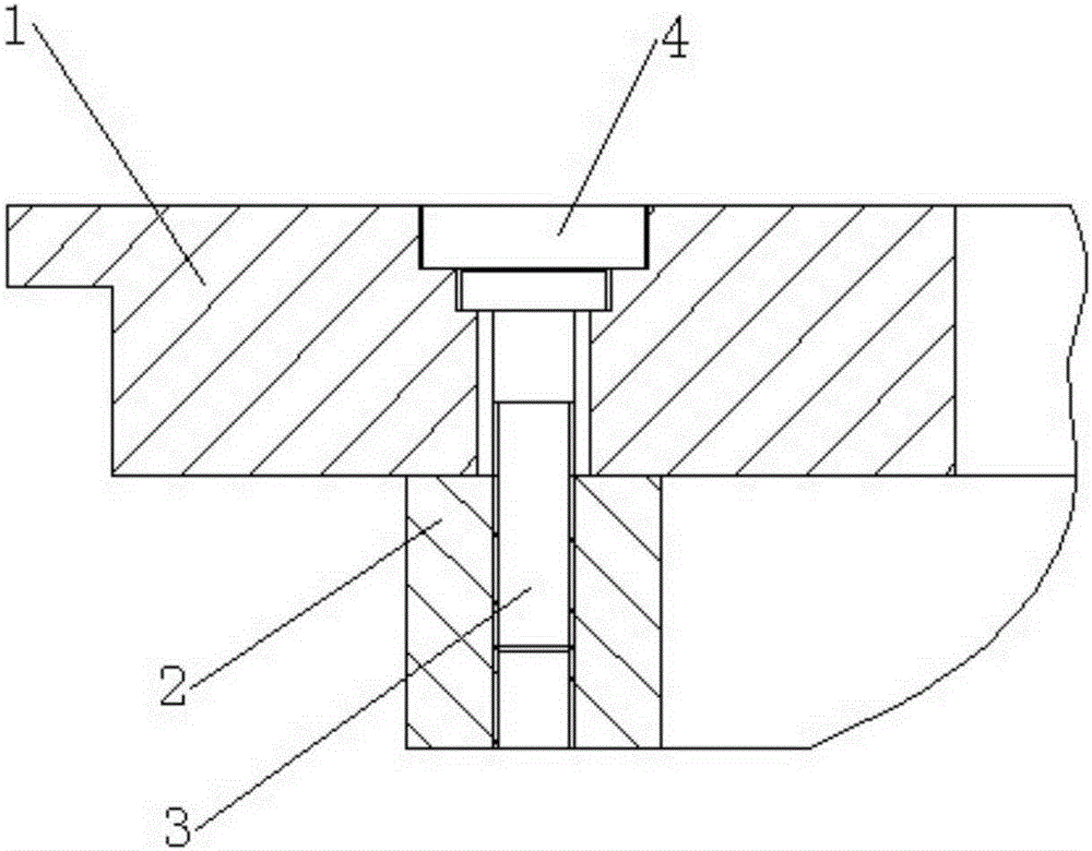
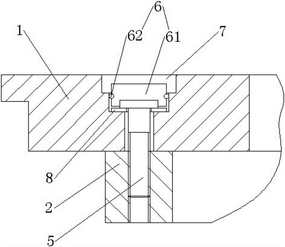
[0028] Such as figure 2 As shown, the plasma etching machine includes a reaction chamber, an ion generating electrode 2 is arranged in the reaction chamber, a support frame 1 is arranged above the ion generating electrode 2 to support the workpiece to be processed, the support frame 1 is provided with mounting holes, and the ion generating electrode 2 A threaded hole is opened in the area corresponding to the mounting hole. The mounting hole and the threaded hole are connected by a screw 5. A sealing unit 6 is provided in the axial direction of the screw 5 and above the screw 5, and the sealing unit 6 is used to seal the mounting hole A sealing cap 7 is provide...

Embodiment 2

[0041] This embodiment provides a plasma etching machine, which is different from the plasma etching machine of Embodiment 1 in that: the plasma etching machine provided in this embodiment does not have a sealing cap structure, and the mounting holes are arranged in order from top to bottom There are sealing units and screws.

[0042] The specific structure of the plasma etching machine provided in this embodiment is as follows Figure 4 As shown, the mounting holes opened on the support frame 1 are stepped holes, including a first-stage hole and a second-stage hole located above the first-stage hole. The second-stage hole has a larger diameter than the first-stage hole. The ion generating electrode 2 is provided with a threaded hole in a region corresponding to the mounting hole. The mounting hole and the threaded hole are connected by screws 5. Correspondingly, the main body of the screw 5 is located in the threaded hole and the first stage hole, and the head of the screw 5 i...


PUM


Abstract

The invention, which belongs to the technical field of the semiconductor manufacturing, provides a plasma etching machine comprising a reaction cavity. An ion generation electrode is arranged in the reaction cavity; a support frame is arranged on the ion generation electrode to support a to-be-processed workpiece; and a mounting hole is formed in the support frame. A screw hole is formed in a region, corresponding to the mounting hole, of the ion generation electrode. The mounting hole and the screw hole are connected by a bolt. A sealing unit is arranged on the bolt at the axial direction of the bolt and is used for sealing the mounting hole. According to the plasma etching machine, a plasma on the support frame can be prevented from entering the screw hole of the ion generation electrode effectively for long time, thereby avoiding damages of the ion generation electrode by the plasma.

Description

Technical field [0001] The invention belongs to the technical field of semiconductor manufacturing, and specifically relates to a plasma etching machine. Background technique [0002] In the existing plasma etching machine, such as figure 1 As shown, the support frame 1 inside the reaction chamber and the ion generating electrode 2 are usually connected by mounting screws 3. In order to prevent the plasma above the mounting hole from contacting the ion generating electrode 2 through the gap between the mounting screw 3 and the inner wall of the mounting hole and causing damage to the ion generating electrode 2, a ceramic sheet 4 is arranged above the mounting screw 3 in the mounting hole. [0003] The inventor found at least the following problems in the prior art: [0004] First, the ceramic sheet 4 has been under plasma bombardment, and its diameter and thickness are constantly depleted, causing the plasma to easily enter the mounting hole and damage the ion generating electrode 2...

Claims


Application Information

Patent Timeline
Patent Type & Authority Applications(China)
IPC IPC(8): H01L21/67H01L21/3065H01J37/32
CPCH01J37/32H01L21/3065H01L21/67011H01L21/67121
Inventor 欧飞杨晓峰谌泽林刘学光万稳
Owner BOE TECH GRP CO LTD
Why Eureka
Try Eureka