Mixed carrier-based multi-level PWM method

A modulation method and mixed carrier technology, applied in electrical components, output power conversion devices, irreversible DC power input conversion to AC power output, etc., can solve the problems of reducing high-voltage units, power backflow, etc., and improve harmonics The effect of the characteristic

Active Publication Date: 2016-01-06
NANJING UNIV OF AERONAUTICS & ASTRONAUTICS
View PDF3 Cites 10 Cited by
  • Summary
  • Abstract
  • Description
  • Claims
  • Application Information

AI Technical Summary

Problems solved by technology

[0006] The purpose of the present invention is to propose a hybrid carrier-based multi-level PWM modulation method suitable for hybrid cascaded H-bridge seven-level inverters. On the one hand, it solves the inherent power backfeeding problem of traditional hybrid modulation strategies, and on the other hand, it reduces The switching frequency of the high-voltage unit, while increasing the equivalent output frequency of the low-voltage unit, can ensure good output characteristics of the system without increasing the system cost, and improve the efficiency and practicability of the multi-level inverter

Method used


Image

  • Mixed carrier-based multi-level PWM method
  • Mixed carrier-based multi-level PWM method
  • Mixed carrier-based multi-level PWM method

Examples


Embodiment Construction

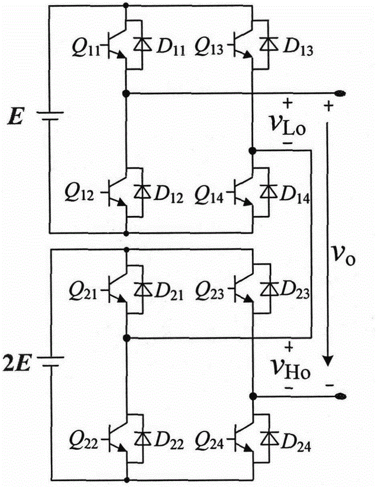
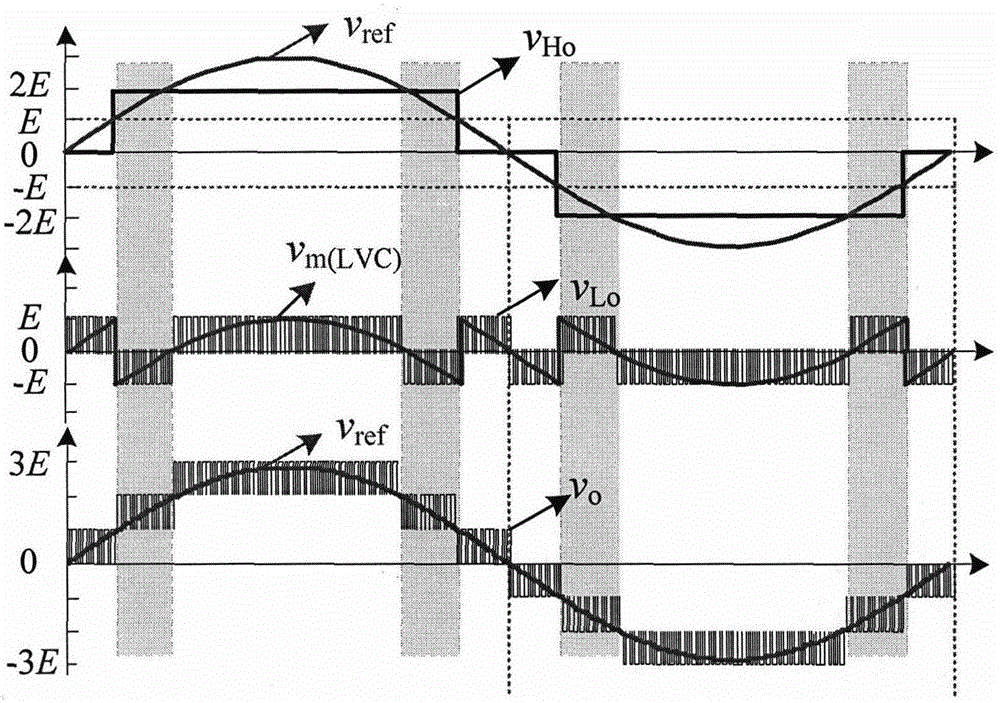
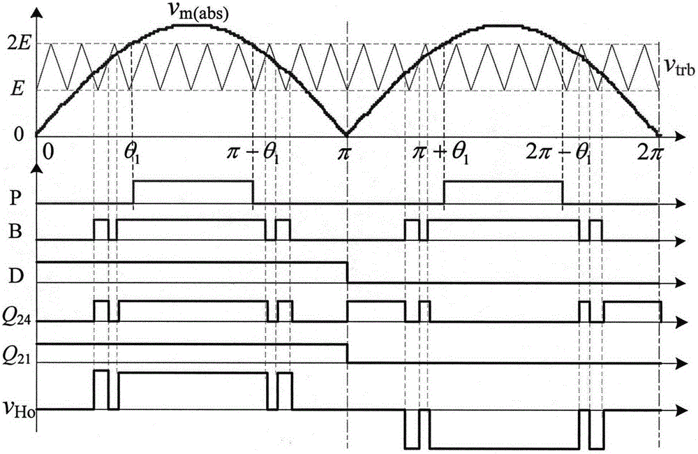
[0023] The multi-level PWM modulation method based on the mixed carrier wave applicable to the hybrid cascaded H-bridge seven-level inverter proposed by the present invention, its PWM waveform synthesis method in each voltage interval is as shown in Table 1:

[0024] Interval [+2E, +3E]: The constant output level of the high-voltage unit is +2E, and the frequency of the low-voltage unit is f 1 Carrier frequency multiplied modulation, the output PWM waveform, its equivalent output frequency is 2f 1 . The final synthesized inverter output is PWM waveform, the equivalent output frequency is 2f 1 .

[0025] Interval [+E, +2E]: This interval adopts frequency f 2 (f 2 ≤f 1 ) carrier for modulation. The output voltage polarity of the high-voltage unit and the low-voltage unit are the same, and the output voltages are complementary, that is, when the output level of the high-voltage unit is 0, the output level of the low-voltage unit is +E, and when the output level of the h...


PUM


Abstract

The invention discloses a mixed carrier-based multi-level PWM method. The method first takes the absolute value of a reference sinusoidal signal v<ref> to obtain a modulation signal v<m(abs)> of a high voltage unit, and then obtains a modulation signal v<m(LVC)> of a low voltage unit through comparison and operation. The modulation signal of the high voltage unit is compared with a triangular carrier signal v<trb> whose frequency is f2 to obtain a logic pulse signal B, and is compared with a voltage reference signal v<rh> to obtain a logic pulse signal P. The modulation signal of the low voltage unit is compared with triangular signals v<tra> and v<trc> whose frequency is f1 to obtain logic pulse signals A and C. The reference sinusoidal signal is compared with zero voltage to obtain a polarity pulse signal D. Then the four logic pulse signals and the polarity pulse signal pass through a driving logic distribution unit to generate an optimized PWM drive signal. The method provided by the invention does not have the problem of power backflow, and optimizes equivalent switching frequency of high- and low-voltage units of an inverter.

Description

technical field [0001] The invention belongs to the technical field of PWM of multi-level converters, and in particular relates to a multi-level PWM modulation method based on a mixed carrier wave suitable for a hybrid cascaded H-bridge seven-level inverter with a voltage ratio of 1:2. Background technique [0002] In the field of power electronics, especially in high-voltage and high-power applications, multilevel converters have received more and more attention and applications. Compared with traditional two-level converters, multi-level converters have obvious advantages in improving the quality of output voltage waveforms and reducing the voltage stress of switching tubes. In the late 1990s, Indian scholar M.D.Manjrekar proposed a hybrid cascaded H-bridge seven-level inverter topology with a DC side voltage ratio of 1:2. Its structure is as follows: figure 1 shown. This topology is developed from the traditional equal-voltage cascaded H-bridge inverter. It can output m...

Claims


Application Information

Patent Timeline
Patent Type & Authority Applications(China)
IPC IPC(8): H02M7/49H02M7/493H02M7/5395
Inventor 陈仲许亚明刘亚云那显龙
Owner NANJING UNIV OF AERONAUTICS & ASTRONAUTICS
Why Eureka
Try Eureka