Cross-coupled filter

A cross-coupling and filter technology, applied in the field of filters, can solve the problems of poor insertion loss and rejection, poor filter insertion loss, single initial direction of resonators, etc., to achieve miniaturization and improve Q value , The effect of maintaining product quality

Pending Publication Date: 2021-02-09
PROSE TECH CO LTD
View PDF3 Cites 0 Cited by
  • Summary
  • Abstract
  • Description
  • Claims
  • Application Information

AI Technical Summary

Problems solved by technology

However, this structure still has the following disadvantages: 1. Although the multiple bending of the resonator is conducive to miniaturization, relatively speaking, the decrease in the Q value leads to the deterioration of the insertion loss in the electrical performance of the filter; and when the mold is opened to make the product , the component volume is relatively smaller than ordinary filters and there are bends, and there is a possibility of deformation during die-casting; 2. It is necessary to improve the harmonic characteristics of the 2-fold frequency
However, this structure still has the following disadvantages: 1. Although the multiple bending of the resonator is conducive to miniaturization, relatively speaking, the decrease in the Q value leads to the deterioration of the insertion loss in the electrical performance of the filter; 2. In order to strengthen the resonance of each layer For the amount of coupling between units, the window on the shielding layer must be opened very large, which brings certain restrictions to increasing the bandwidth; 3. The initial direction of the resonator is single, and the change of the coupling form is limited
[0008] Therefore, it is necessary to propose a new type of miniaturized and lightweight filter to solve the problems of insertion loss and suppression in the electrical performance of the above-mentioned filter, the possibility of deformation during die-casting, and the need for double frequency Harmonic improvement and other issues

Method used


Image

  • Cross-coupled filter
  • Cross-coupled filter
  • Cross-coupled filter

Examples


Embodiment 1

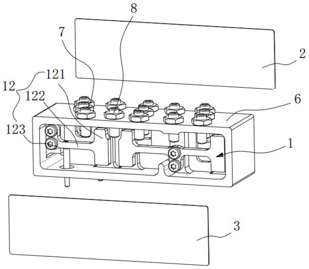
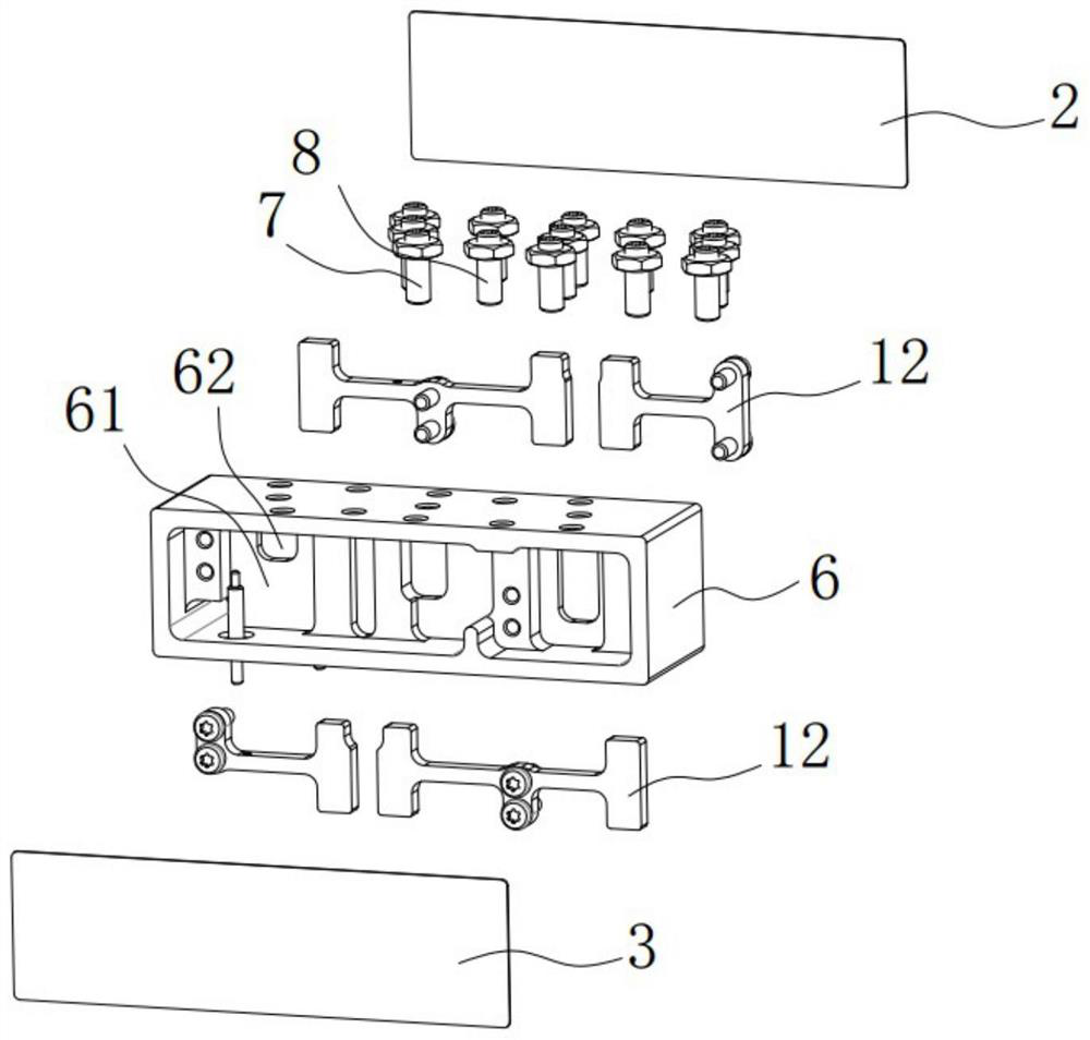
[0081] combine Figure 1 ~ Figure 3 As shown, a cross-coupled filter according to Embodiment 1 of the present invention includes a resonant structure 1, a first cover plate 2, and a second cover plate 3, wherein the first cover plate 2 and the second cover plate 3 are respectively covered on On the front and rear sides of the frame 6 , a closed filter cavity is formed in the frame, and the resonant structure 1 is separately installed in the frame 6 . Wherein, the structures of the first cover plate 2 and the second cover plate 3 can refer to the above description, and will not be repeated here. The structure of the resonant structure 1 will be described in detail below.

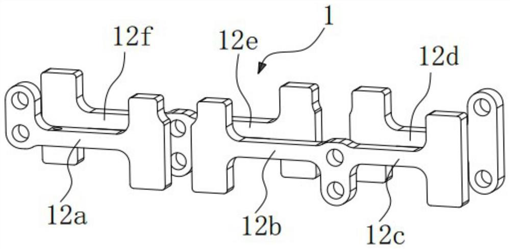
[0082] Such as image 3 As shown, the filter formed by the resonant structure 1 in Embodiment 1 of the present invention is a 6-order filter, which includes two rows of resonant units. The two rows of resonant units are not on the same plane, and are specifically arranged in layers along the front and rear ...

Embodiment 2

[0090] Such as Figure 5 As shown, a cross-coupled filter in Embodiment 2 of the present invention is an alternative implementation of Embodiment 1 above, and the filter formed by the resonant structure 1 in Embodiment 2 of the present invention is also a 6-order filter, and its It also includes two rows of resonant units, the two rows of resonant units are not on the same plane, specifically arranged in layers along the front and rear directions of the frame. Different from the first embodiment, the resonator 12a, the resonator 12b, the resonator 12f and the resonator 12e in the second embodiment constitute the minimum resonance structure A mentioned above. In this minimum resonant structure A, the resonator 12a and the resonator 12b in the same row are mainly electrically coupled, the resonator 12f and the resonator 12e in the same row are mainly magnetically coupled, and the resonator 12a and the resonator Cross-coupling occurs between 12f.

[0091] Except for the minimum...

Embodiment 3

[0094] Such as Figure 6 As shown, a cross-coupling filter according to Embodiment 3 of the present invention is also an alternative implementation manner of Embodiment 1 above. The difference from Embodiment 1 is that the two rows of resonant units in Embodiment 3 are located on the same plane, and the arrangement structure and coupling mode of the other six resonators are the same as those in Embodiment 1 above, and will not be repeated here.


PUM


Abstract

The invention discloses a cross-coupled filter, which comprises a minimum resonance structure, the minimum resonance structure is composed of four resonators, in the minimum resonance structure, two resonators in the same row form a group, and the two resonators in the same row are mainly electrically coupled or magnetically coupled; the two resonators in the same column are electromagnetically mixed and coupled; and the coupling polarities of the two groups of resonators of the two rows of resonance units are opposite, and at least one cross coupling is formed. According to the invention, miniaturization and light weight are realized in terms of structural characteristics, and low loss and good harmonic characteristics are realized in terms of electrical performance.

Description

technical field [0001] The present invention relates to a filter, in particular to a cross-coupling filter. Background technique [0002] The recent demand trend for filters is miniaturization and high quality. In particular, the communication components used in the small base stations of 5G communications are smaller in size and more in demand than the previous macro base station products. Therefore, the components used in the product must also achieve high-quality miniaturization, light weight, and a structure suitable for mass production. [0003] The filters currently used in small base stations are usually dielectric waveguide filters and traditional metal coaxial filters. The dielectric waveguide filter can be miniaturized and lightweight, and the manufacturing cost is low, but its loss and harmonic characteristics are worse than that of the metal coaxial filter. Traditional metal coaxial filters have better loss and harmonic characteristics than dielectric waveguide...

Claims


Application Information

Patent Timeline
Patent Type & Authority Applications(China)
IPC IPC(8): H01P1/20H01P1/208
CPCH01P1/20H01P1/208
Inventor 李敦穁罗仁虎尹泽李强
Owner PROSE TECH CO LTD
Why Eureka
Try Eureka