Eureka AIR delivers breakthrough ideas for toughest innovation challenges, trusted by R&D personnel around the world.

On-line sludge discharge apparatus for crude-oil storage tank

A crude oil storage tank and sludge discharge device technology, which is applied to the feeding/discharging device of the sedimentation tank, etc., can solve the problems of affecting the oil-water separation effect, long production shutdown time, and high labor intensity of workers, so as to prolong the gravity sedimentation separation time. , The device has the effect of good reliability and simple structure

Active Publication Date: 2016-01-13
WUHAN INSTITUTE OF TECHNOLOGY +1
View PDF6 Cites 5 Cited by
  • Summary
  • Abstract
  • Description
  • Claims
  • Application Information

AI Technical Summary

Problems solved by technology

[0002] During oilfield production and operation, the produced fluid contains a large amount of solid particles, which gradually deposit on the bottom of the tank to form a mud surface. When it reaches a certain thickness, the effective height of the storage tank will decrease accordingly, which will cause the gravity of oil and water to The time of sedimentation and separation is reduced, which affects the effect of oil-water separation and increases the burden on the sewage treatment system
At present, the traditional method of manually entering the tank for mud cleaning is mostly used. However, this method is not only labor-intensive, but also brings certain environmental pollution and safety hazards. At the same time, the shutdown time is long, which hinders normal production and related activities. equipment operation

Method used


Image

  • On-line sludge discharge apparatus for crude-oil storage tank
  • On-line sludge discharge apparatus for crude-oil storage tank
  • On-line sludge discharge apparatus for crude-oil storage tank

Examples


Embodiment Construction

[0024] In order to make the object, technical solution and advantages of the present invention clearer, the present invention will be further described in detail below in conjunction with the accompanying drawings and embodiments. It should be understood that the specific embodiments described here are only used to explain the present invention, not to limit the present invention.

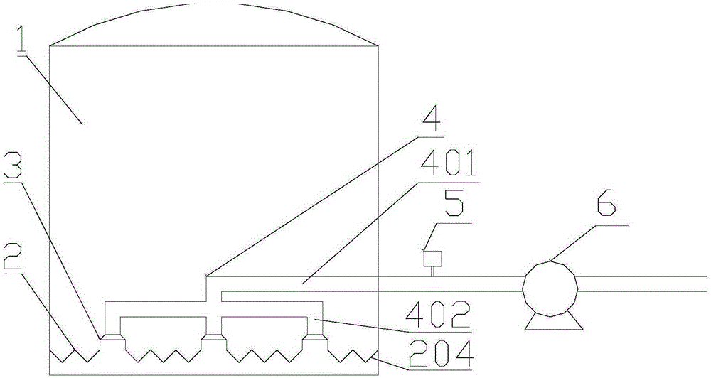
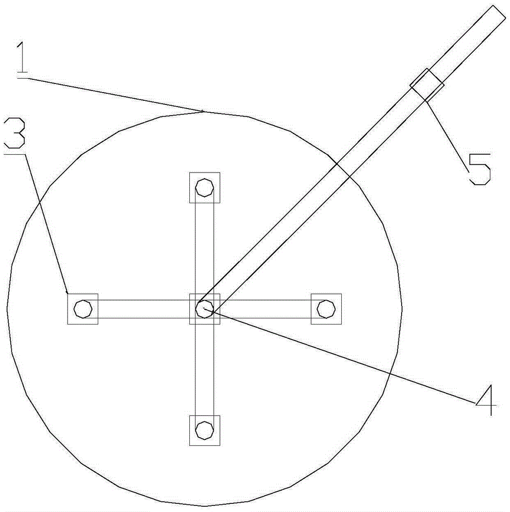
[0025] Such as Figure 1-Figure 3 As shown, an online sludge discharge device for a crude oil storage tank, the device is arranged at the lower part of a crude oil storage tank 1, and the device includes a conical plate 2, a mud collection cavity 3 and a mud discharge pipe 4 arranged sequentially from bottom to top;

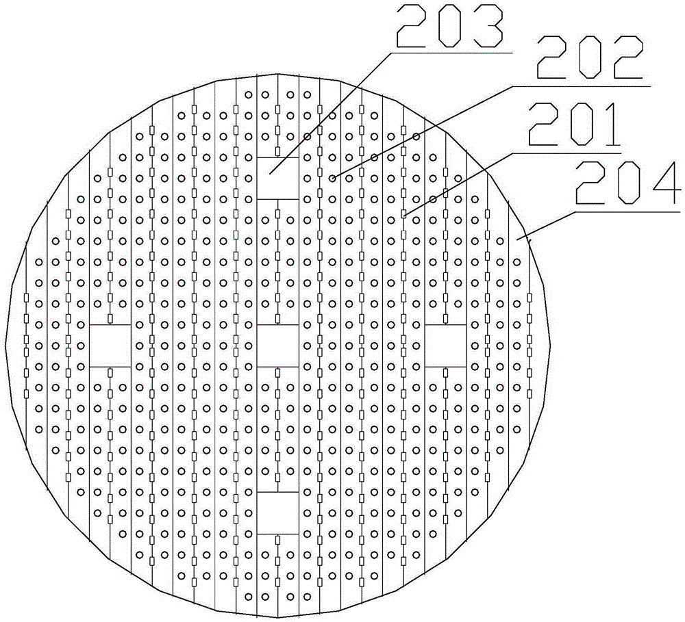
[0026] The conical plate 2 is fixedly installed on the inner wall of the crude oil storage tank at a certain height from the bottom of the crude oil storage tank 1. The cross-sectional shape of the conical plate 2 is a triangular zigzag shape. The bottom of the tooth of the conical pl...


PUM


Abstract

A disclosed on-line sludge discharge apparatus for a crude-oil storage tank comprises a taper plate, sludge-collecting cavities and a sludge discharge pipe; the taper plate is fixedly installed at a position, keeping a certain distance from the crude-oil storage tank bottom, on the crude-oil storage tank inner wall, and the cross section of the taper plate is in the shape of a triangle zigzag; the tooth bottom of the taper plate is provided with multiple sludge settling holes, and the tooth lateral side of the taper plate is provided with multiple sludge discharge holes; the taper plate is provided with multiple installation holes; the multiple sludge-collecting cavities are respectively installed at the installation holes; the sludge discharge pipe comprises a main pipe and multiple branch pipes connected with the main pipe, and each branch pipe is installed at the corresponding sludge collecting cavity; and the outer end of the main pipe stretches out of the crude-oil storage tank, and the outer end of the main pipe is provided with an electrically operated valve and a slag slurry pump. The apparatus is simple in structure, is capable of timely removing sludge in the tank, realizes blind-angle-free sludge discharge and production-ceaseless sludge discharge at a normal production state, and mitigates burden of a sewage processing system.

Description

technical field [0001] The invention relates to a crude oil storage tank cleaning device, in particular to an online sludge discharge device for a crude oil storage tank. Background technique [0002] During oilfield production and operation, the produced fluid contains a large amount of solid particles, which gradually deposit on the bottom of the tank to form a mud surface. When it reaches a certain thickness, the effective height of the storage tank will decrease accordingly, which will cause the gravity of oil and water to The time of sedimentation and separation is reduced, which affects the effect of oil-water separation and increases the burden on the sewage treatment system. At present, the traditional method of manually entering the tank for mud cleaning is mostly used. However, this method is not only labor-intensive, but also brings certain environmental pollution and safety hazards. At the same time, the shutdown time is long, which hinders normal production and ...

Claims


Application Information

Patent Timeline
Patent Type & Authority Applications(China)
IPC IPC(8): B01D21/24
Inventor 喻九阳高海徐建民郑小涛林纬王成刚
Owner WUHAN INSTITUTE OF TECHNOLOGY
Why Eureka
Eureka Blog
Learn More