
Gear clamp for casting surface treatment

A technology of surface treatment and gear fixtures, which is applied in the direction of workpiece clamping devices and manufacturing tools, can solve the problems of increased installation space, large pull rod diameter, and inconvenient pull rods, etc., to achieve improved efficiency, simple operation steps, and control The effect of automation

Inactive Publication Date: 2016-01-13
CHONGQING YINGRUISHENG DIE CASTING
View PDF0 Cites 0 Cited by
  • Summary
  • Abstract
  • Description
  • Claims
  • Application Information

AI Technical Summary

Problems solved by technology

However, the pull rods in this solution are not very convenient in actual use, and the large diameter of the pull rods increases the installation space and makes the layout unreasonable

Method used


Image

  • Gear clamp for casting surface treatment

Examples


Embodiment Construction

[0012] The present invention will be described in further detail below by means of specific embodiments:

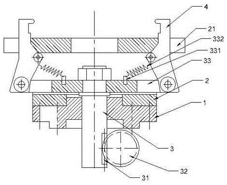
[0013] The reference signs in the accompanying drawings of the description include: lower machine base 1, upper machine base 2, clamping table 21, slide bar 3, rack 31, gear 32, horizontal plate 33, pin 331, tension spring 332, clamping jaws 4.

[0014] The embodiment is basically as attached figure 1 Shown:

[0015] The gear fixture for surface treatment of castings in this program includes a slide bar 3 and a jaw 4. The slide bar 3 passes through the lower machine base 1 and is inserted into the through hole opened on the machine base. The slide bar 3 is processed with teeth. Bar 31, one side of the slide bar 3 is arranged with a gear 32 cooperating with the rack 31, the gear 32 is connected with a motor, the upper end of the slide bar 3 is connected with a horizontal plate 33, and the two ends of the horizontal plate 33 are respectively hinged with clips. Claw 4, th...


PUM


Abstract

The invention relates to the technical field of clamps and discloses a gear clamp for casting surface treatment. The gear clamp comprises a machine base, a sliding rod and clamping jaws, wherein the sliding rod penetrates through the machine base and is sleeved with a through hole in the machine base; the sliding rod is provided with a rack; a gear connected with the rack in a matched mode is arranged on one side of the sliding rod; the gear is connected with a motor; one end of the sliding rod is connected with a transverse board; the two ends of the transverse board are provided with the clamping jaws in a hinged mode; the middles of the clamping jaws are hinged to the machine base; a tension spring is connected between each clamping jaw and the transverse board; the machine base is further provided with a clamping table located between the two clamping jaws. Compared with the prior art, the motor and gear drive replaces drive of a pull rod, so that the clamping operation steps are simpler, control is more automatic, and efficiency is improved.

Description

technical field [0001] The invention relates to the technical field of clamps. Background technique [0002] Surface treatment is a method of artificially forming a surface layer on the surface of a base material with mechanical, physical and chemical properties different from that of the base. The purpose of surface treatment is to meet the corrosion resistance, wear resistance, decoration or other special functional requirements of the product. For metal castings, our more commonly used surface treatment methods are mechanical grinding, chemical treatment, surface heat treatment, surface spraying, and surface treatment is to clean, sweep, deburr, degrease, and descale the surface of the workpiece. For the castings after die casting, simple surface treatment is required to make the castings meet certain size standards and requirements, which are convenient for storage and transportation, and also meet the requirements of sales. [0003] The fixtures manufactured for the s...

Claims


Application Information

Patent Timeline
IPC IPC(8): B25B11/00
CPCB25B11/00
Inventor 王燕
Owner CHONGQING YINGRUISHENG DIE CASTING
Learn More