Outer flange structure of air flue of railway vehicle

A rail vehicle and outer flange technology, which is applied in flange connection, railway vehicle heating/cooling, railway vehicle body parts, etc., can solve problems such as unsatisfactory sealing conditions and inability to achieve full welding of the outer flange of the air duct, etc. Achieve the effect of good use value, simple structure and easy process realization

Active Publication Date: 2016-01-13
CRRC NANJING PUZHEN CO LTD
View PDF8 Cites 1 Cited by
  • Summary
  • Abstract
  • Description
  • Claims
  • Application Information

AI Technical Summary

Problems solved by technology

[0004] The development of rail transit is changing with each passing day, and there are more and more types of rail vehicles. The height of the roof of each rail vehicle project and the height of the flat roof for installing air conditioners are also different. In recent years, there have been many cases where the outer flange of the air duct is full Situations where welding cannot be achieved
In order to ensure the sealing performance of the car body, the interface between the lower opening of the outer flange of the air duct and the top of the middle part is glued, but the sealing is not ideal. It is necessary to innovate a structure of the outer flange of the air duct at the top of the middle part, which can meet the needs of both the inside and outside of the air conditioner. The installation requirements of the air duct and the sealing performance of the steel structure of the car body here

Method used


Image

  • Outer flange structure of air flue of railway vehicle
  • Outer flange structure of air flue of railway vehicle
  • Outer flange structure of air flue of railway vehicle

Examples


Embodiment Construction

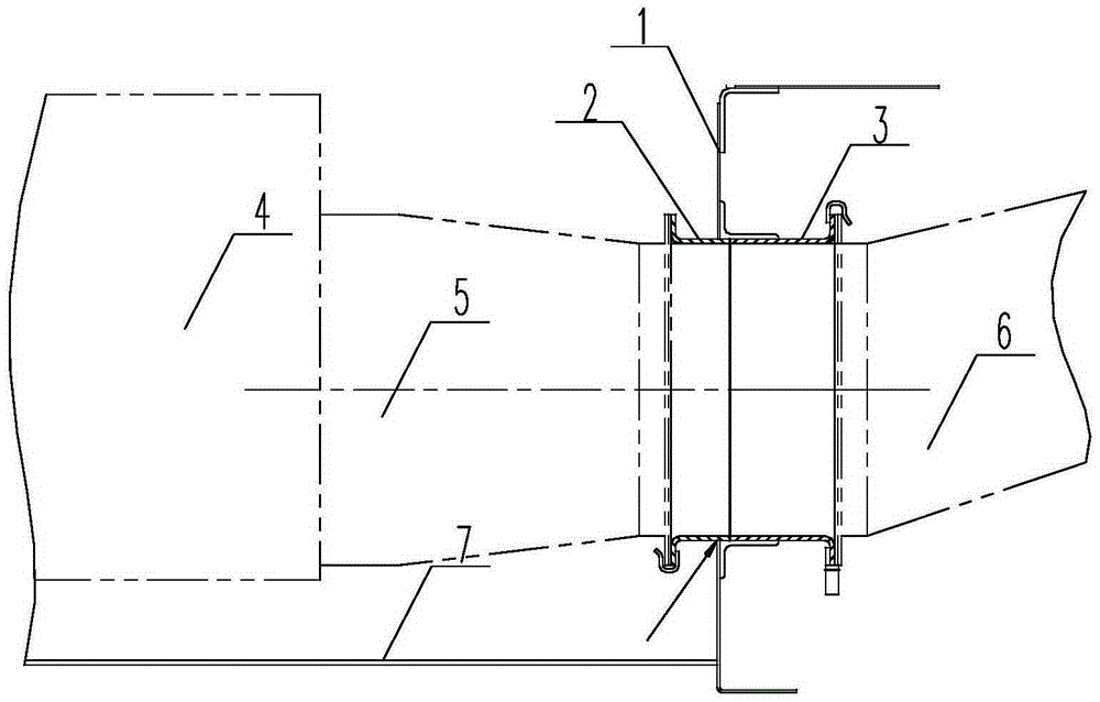
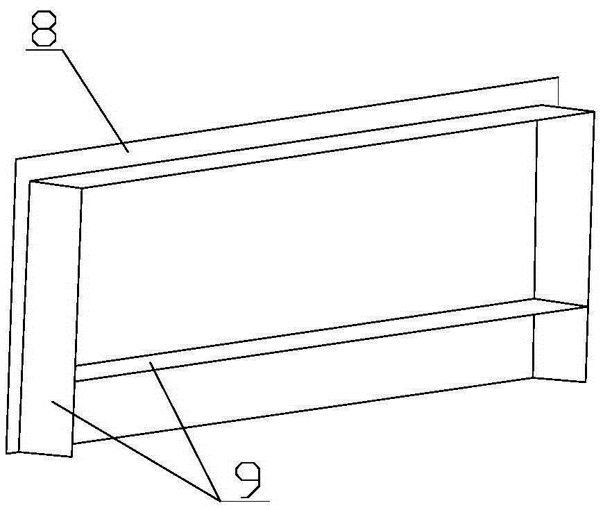
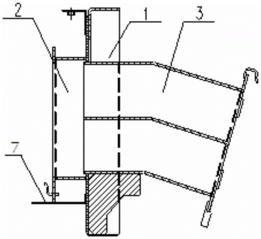
[0019] like Figure 1 to Figure 4 As shown, the outer flange structure of the rail vehicle air duct in this embodiment includes an outer flange tube 8 and an outer flange edge 9, the outer flange tube 9 is surrounded by four wing plates, and the left and right side wing plates of the outer flange tube 9 are connected to each other. parallel, and its bottom end is flush with the bottom end of the outer flange 8, the left and right wing plates of the outer flange 9 and the outer flange 8 fall together on the flat roof 7 of the vehicle, and the four sides of the outer flange 9 A wing plate is welded and fixed with the vehicle middle end top plate 1; the bottom end of the left and right sides wing plates of the outer flange tube 9 and the bottom end of the outer flange side 8 are welded on the flat roof plate of the vehicle.

[0020] In order to achieve sealing, in this embodiment, full welding is used between the four wing plates of the outer flange cylinder 9 and the roof plate ...


PUM


Abstract

The invention relates to an outer flange structure of an air flue of a railway vehicle. The outer flange structure comprises an outer flange barrel and an outer flange edge, wherein the outer flange barrel is defined by four wing plates, the bottom ends of the left wing plate and the right wing plate of the outer flange barrel are aligned at the bottom end of the outer flange edge, and the left wing plate and the right wing plate of the outer flange barrel and the outer flange edge are jointly located on a vehicle flat roof plate; and the four wing plates of the outer flange barrel and a top plate of the middle end of the vehicle are fixedly welded. According to the outer flange structure of the air flue of the railway vehicle, innovation is made on the basis of a conventional structure; the brand-new design structure and the brand-new welding process are adopted, the caliber of the outer flange barrel of the air flue is enlarged, and the wing plates on the two sides and the lowermost edge of the outer flange edge extend to the flat roof plate. When a roof is positively installed, an outer flange of the air flue is directly located on the flat roof, the wing plates of the outer flange barrel of the air flue and the lowermost edge of the flange are directly welded to the flat roof plate, the lateral faces of the wing plates of the outer flange of the air flue and the top plate at the middle end are welded, and therefore the outer flange structure of the air flue can meet the installation requirement of an outer air flue of an air-conditioner and the requirement for the sealing performance of a vehicle body steel structure at the same time; and in addition, the structure is simple, and the process is easy to implement.

Description

technical field [0001] The invention relates to an outer flange structure of a rail vehicle air duct, and belongs to the technical field of rail vehicle body structure design. Background technique [0002] The flat top 7 in the steel structure of the rail passenger car roof is mainly used to install the air conditioning unit 4, the middle end top 1 divides the air duct connected to the air conditioner into two, the outer air duct 5 is outside the middle end top 1, and the middle end top 1 is the outer air duct 5. Inside the top 1 is the inner air duct 6, and the two are connected by the inner and outer flanges 3 and 2 of the steel structure air duct, such as figure 1 shown. [0003] The inner and outer flanges of the air duct are connected at the top of the middle part. In order to ensure the sealing performance after connection, the outer flange of the air duct needs to be fully welded with the top of the middle part ( figure 1 Arrow), but the premise of full welding is t...

Claims


Application Information

Patent Timeline
Patent Type & Authority Applications(China)
IPC IPC(8): B61D27/00F16L23/12
Inventor 王小霞杜彦品杨智朋高健飞王潇雨牛永刚王世博吴利民
Owner CRRC NANJING PUZHEN CO LTD
Why Eureka
Try Eureka