Crane encoder mounting structure

An installation structure and encoder technology, applied in the directions of traveling mechanism, transportation and packaging, load hanging components, etc., can solve the complex installation operation, the inability to accurately collect the wheel linear speed data, and the coaxial accuracy of the installation hole and the wheel shaft. higher question

Inactive Publication Date: 2016-01-13
CHONGQING KESHUO HOISTING EQUIP
View PDF7 Cites 1 Cited by
  • Summary
  • Abstract
  • Description
  • Claims
  • Application Information

AI Technical Summary

Problems solved by technology

[0003] Existing crane wheel encoders are mainly directly fixedly connected to the wheel shaft through a coupling, which requires coaxial mounting holes on the wheel shaft, so that the installation structure of the encoder takes up a large space, and the installation operation is complicated. The coaxial precision between the hole and the wheel axle is required to be high. Once the accuracy error is large, the data collected by t

Method used


Image

  • Crane encoder mounting structure
  • Crane encoder mounting structure
  • Crane encoder mounting structure

Examples


Embodiment 1

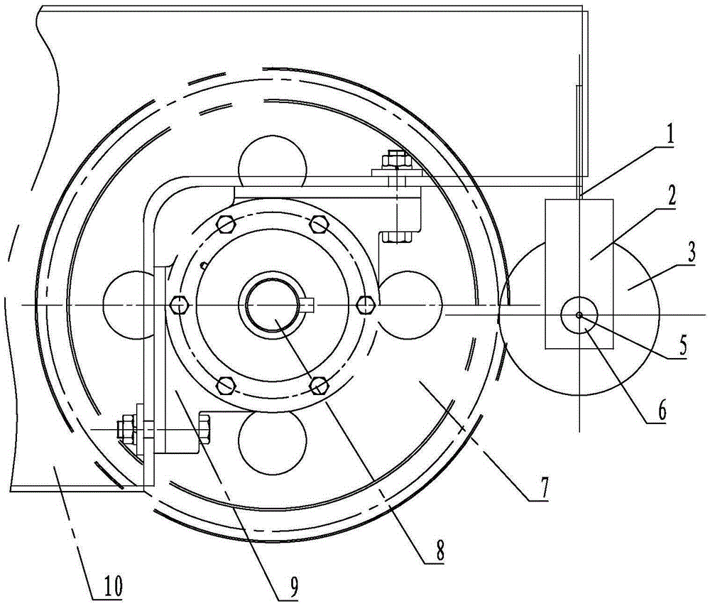
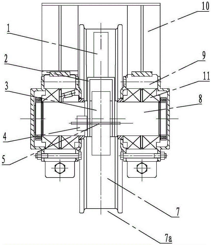
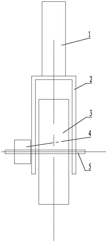
[0021] Such as figure 1 , figure 2 , image 3 and Figure 4 As shown, the present invention includes a wheel shaft 8 and a wheel 7 fixedly sleeved on the wheel shaft 8, and first bearings 11 are fixedly sleeved at both ends of the wheel shaft 8, and each of the first bearings 11 is installed on a corresponding In the bearing housing 9, these are all identical with the prior art, do not repeat them here. It also includes a "U"-shaped mounting frame 2 relatively fixed to the bearing box 9, and a shield 10 is covered on the wheel 7, and the shield 10 is fixedly connected with the bearing box 9, and at the closed end of the mounting frame 2 A mounting plate 1 is fixedly connected to the outside. In this embodiment, the mounting plate 1 is preferably arranged vertically, and the upper end of the mounting plate 1 is fixed to the shield 10 by bolts. A rotating shaft 5 is pierced between the two side plates of the mounting frame 2, and a second bearing 6 is fixed on the two side ...

Embodiment 2

[0024] Such as Figure 5 As shown, the mounting plate 1 is arranged obliquely, and the end of the mounting plate 1 away from the mounting frame 2 is fixed to the shield 10 by bolts. Other structures of this embodiment are the same as those of Embodiment 1, and will not be repeated here.


PUM


Abstract

The invention discloses a crane encoder mounting structure which comprises a wheel axle and a crane wheel and further comprises a U-shaped mounting frame, wherein the wheel axle is fixedly sleeved with the crane wheel; two ends of the wheel axle are fixedly sleeved with first bearings; each first bearing is mounted in one corresponding bearing housing; the U-shaped mounting frame is oppositely fixed with the bearing housing; a rotating shaft is arranged between two side plates of the mounting frame in a penetrating manner, and is fixedly sleeved with a friction wheel; the friction wheel is coaxial with the rotating shaft; the circumferential side wall of the friction wheel is in contact and matched with that of the crane wheel; an encoder is fixedly connected with one end of the rotating shaft; an input shaft of the encoder is coaxially arranged with the rotating shaft. Through adoption of the crane encoder mounting structure, no mounting hole needs to be formed in the wheel axle and the friction wheel is in direct contact with the crane wheel, so that the accuracy of data acquisition is remarkably improved; besides, the encoder is convenient to mount and operate, and particularly under the circumstance that no mounting hole is formed in a delivered wheel axle, additional arrangement of the encoder can be convenient. Therefore, the crane encoder mounting structure has the characteristics of ingenious concept, simple structure, easiness in transformation and the like.

Description

technical field [0001] The invention belongs to the technical field of cranes, and in particular relates to a crane encoder installation structure. Background technique [0002] At present, during the operation of the crane, the lifting items need to be transported smoothly, reliably and safely; in particular, the speed of large and small vehicles needs to be even after lifting the goods. During the operation of the crane, the speed of the large and small vehicles is consistent with the linear speed of the wheels. Therefore, encoders are installed on the large and small wheels of the crane to monitor the rotation speed of the wheels. [0003] Existing crane wheel encoders are mainly directly fixedly connected to the wheel shaft through a coupling, which requires coaxial mounting holes on the wheel shaft, so that the installation structure of the encoder takes up a large space, and the installation operation is complicated. The coaxial precision between the hole and the whe...

Claims


Application Information

Patent Timeline
IPC IPC(8): B66C9/08B66C13/16
Inventor 王萌赵雁俊程诗英
Owner CHONGQING KESHUO HOISTING EQUIP
Why Eureka
Try Eureka