Reverse thermal bonding technology for making micro and nano fluid system with controllable size

A fluid system, micro-nano technology, applied in micro-structure technology, manufacturing of micro-structure devices, decorative arts, etc., can solve problems such as low success rate, low channel strength, uneven packaging layer, etc., to reduce production costs and experimental operations. Simple, powerful effects

Inactive Publication Date: 2013-06-12
HEFEI UNIV OF TECH
View PDF5 Cites 15 Cited by
  • Summary
  • Abstract
  • Description
  • Claims
  • Application Information

AI Technical Summary

Problems solved by technology

The channel size of traditional thermal bonding technology is difficult to control and is prone to clogging
Since the encapsulation layer polymer is spin-coated on the flexible substrate, the encapsulation layer is necessarily uneven, resulting in low success rate during bonding, uneven channel size and low channel strength

Method used


Image

  • Reverse thermal bonding technology for making micro and nano fluid system with controllable size
  • Reverse thermal bonding technology for making micro and nano fluid system with controllable size

Examples


Embodiment Construction

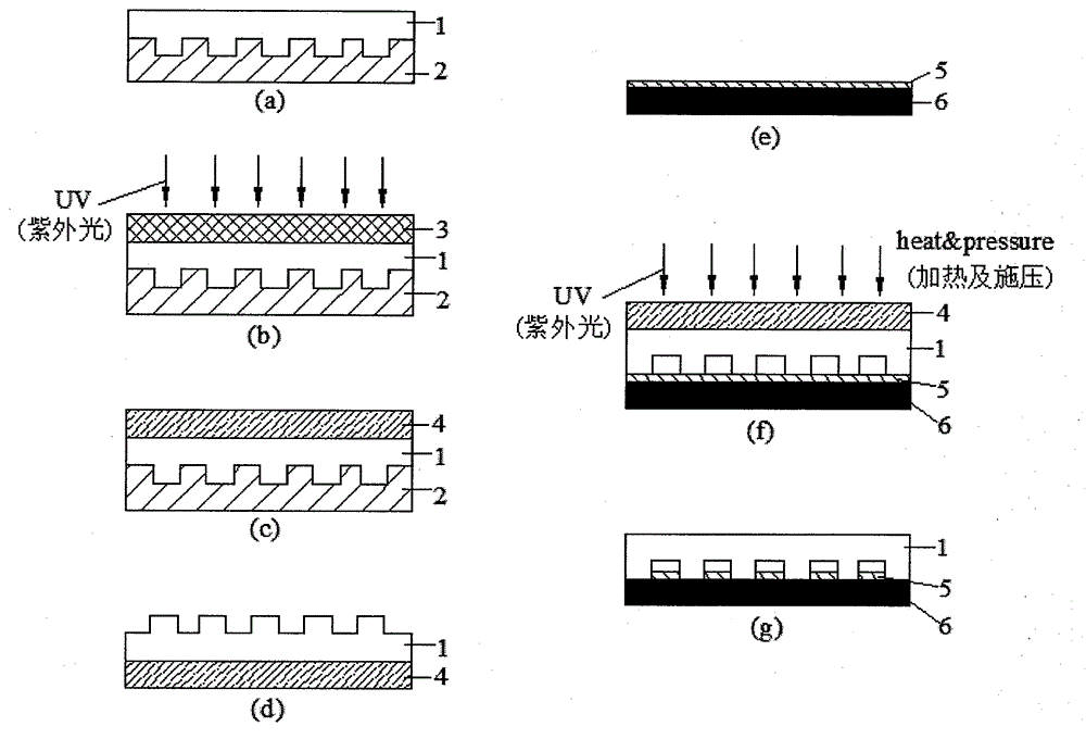
[0030] In this embodiment, the method for fabricating a size-controllable micro-nano fluid system by reverse thermal bonding technology operates as follows:

[0031] 1. Glass grating template in concentrated H 2 SO 4 and hydrogen peroxide mixed solution (volume ratio 2: 1) after soaking for two hours, rinsed with deionized water. Then dry it with nitrogen and put it in an oven at 130°C for 30 minutes. After cooling, spin-coat a layer of DC20 mold release agent on the grating template, and heat it on a hot stage at 85-95°C for 15 minutes. The function of the mold release agent is to change the surface energy of the template, so that the cured SU-8 Photoresist can be easily desorbed. At this point, the pretreatment of the glass template is complete.

[0032] 2. Spin-coat a layer of SU-8 photoresist on the processed grating template. The solvent of this layer of photoresist is toluene, which is used to change the polarity of the SU-8 photoresist. Experiments have proved that ...


PUM

PropertyMeasurementUnit
wavelengthaaaaaaaaaa

Abstract

The invention discloses a reverse thermal bonding technology for making micro and nano fluid system with controllable size. The technology comprises steps of: coating a pretreated grating template with a layer of SU 8 photoresist; copying a graph to the SU-8 photoresist through a reverse embossing technology; then tearing off the cured SU-8 photoresist by using an adhesive UV tape according to different adhesion among interfaces, so as to successfully transfer the graph to a flexible UV adhesive tape; spinning a thin layer of SU-8 photoresist on another Si sheet to form a sealing layer Si substrate; covering the prepared SU-8 adhesive graphic structure layer on the Si substrate; and preparing the micro and nano fluid system through the reverse bonding technology. The invention combines an embossing technology and a bonding technology together, and has advantages of simple operation, no requirement on high temperature and high pressure, controllable channel size and no clogging; and a low manufacturing cost is conducive to mass production.

Description

1: Technical field [0001] The invention belongs to the technical field of micro-nano fluid system production, and relates to a preparation method of a micro-fluid control system. Two: background technology [0002] A micro-nano fluid system is generally defined as a fluid flow channel in which the cross-section of at least one dimension is in the micro-nano size range. Microsystem technology is an important pillar supporting modern high-tech industries. As one of the micro-system technologies, the microfluidic system is a hot research field in recent years. The micro-analysis system developed based on the microfluidic system technology has been successfully used in fluid transport, heat and mass transfer simulation, chemistry, biological science and DNA detection and other fields have broad development prospects. [0003] At present, the materials of micro-nanofluidic system are mainly silicon and its compounds. The common method is to use electron beam lithography or focu...

Claims


Application Information

Patent Timeline
Patent Type & Authority Applications(China)
IPC IPC(8): B81C1/00
Inventor 王旭迪涂吕星刘玉东陶伟王时飞
Owner HEFEI UNIV OF TECH
Why Eureka
Try Eureka