Novel optical fiber wiredrawing cooling system

A cooling system and optical fiber technology, applied in glass fiber drawing devices, glass manufacturing equipment, manufacturing tools, etc., can solve the problems affecting the cooling effect and optical fiber strength, large fluctuations in coating diameter, large amount of helium gas, etc., to improve thermal efficiency Effect of exchange effect, less helium consumption, stable coating diameter

Active Publication Date: 2016-01-13
ZHONGTIAN TECH FIBER OPTICS +1
View PDF9 Cites 9 Cited by
  • Summary
  • Abstract
  • Description
  • Claims
  • Application Information

AI Technical Summary

Problems solved by technology

The cooling effect is improved by air injection and air extraction, but the processing is difficult and it is inconvenient to clean during production
Using ordinary cooling pipes, the amount of helium is large, and the cooling is uneven. High-speed wire drawing is prone to large fluctuations in coating diameter, and the pores of ordinary tubular cooling pipes are inconvenient to clean, and the cooling cavity not only absorbs internal heat but also absorbs heat from the surrounding environment. heat, thus affecting cooling effect and fiber strength

Method used


Image

  • Novel optical fiber wiredrawing cooling system
  • Novel optical fiber wiredrawing cooling system

Examples


Embodiment Construction

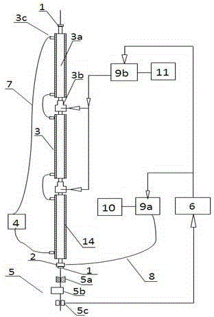
[0021] Such as figure 1 A novel optical fiber drawing cooling system is shown. The novel optical fiber drawing cooling system includes cooling pipe upper and lower shutters 1, drainage plug 2, cooling pipe body 3, cooling water circulation cooling device 4, coating curing device 5, coating Wire diameter control system 6, water pipe 7 and air pipe 8 are composed; the upper end of the shutter 1 under the cooling pipe is installed with a helium drainage plug 2, and the upper end of the helium drainage plug 2 is connected to the cooling pipe body 3, and the lower part of the cooling pipe is a coating Overlay the curing device 5, and the helium drainage plug 2 is connected to the first mass flow meter 9a and the drainage pump 10 in turn through the air pipe 8; the cooling pipe body 3 includes a single cooling pipe 3a and a helium gas inlet device 3b. The cooling pipe body 3 is composed of the single-section cooling pipe 3a described in Sections 3-6. The single-section cooling pipes...


PUM

PropertyMeasurementUnit
diameteraaaaaaaaaa

Abstract

The invention discloses a novel optical fiber wiredrawing cooling system which is used for reducing the temperature before optical fiber coating and avoiding bubble mixing with the coating, ensuring stable coating status of the optical fiber and reducing use quantity of helium gas. The optical fiber wiredrawing cooling system is suitable for high-speed wiredrawing and includes: a cooling tube upper quick-passing gate, a cooling tube lower quick-passing gate, a helium flow guide device, a cooling tube body, a cyclic water cooling device, a coating wire diameter control system, a cooling water tube and a gas tube. The cooling tube body has an inner chamber which is suitable for an optical fiber to pass therethrough; and helium gas is blown into the cooling tube through the special helium gas feeding device which is communicated with the inner chamber and is mounted between the two sections of the cooling tube. A plurality of cooling tube sections are connected through a gas inlet connection apparatus. An outer wall of each cooling tube section is wrapped by a polystyrene foam heat insulation layer. The helium flow guide device draws the gas in the tube at a proper guide flow rate to achieve a best cooling effect. The system is convenient to clean, is good in cooling effect, is high in optical coating quality, is stable in coating layer diameter and is less in helium gas use quantity.

Description

technical field [0001] The invention relates to the field of optical fiber drawing production and manufacturing, and is used for cooling the optical fiber during high-speed drawing production, so that the optical fiber enters the coating system at a suitable temperature to ensure the coating quality of the optical fiber. Background technique [0002] During high-speed wire drawing production, the temperature of the optical fiber when it comes out of the furnace is about 2000 degrees. Directly entering the coating at such a high temperature will cause abnormal coating and production interruption. For this purpose, the optical fiber is forced to be cooled by means of cooling pipes. Chinese patent CN1450009A describes an optical fiber cooling pipe proposed by the applicant Alcatel, which consists of an inner chamber, a set of suction pipes and air intake pipes. The cooling effect is improved by air injection and air extraction, but the processing is difficult and it is inconve...

Claims


Application Information

Patent Timeline
Patent Type & Authority Applications(China)
IPC IPC(8): C03B37/02
CPCC03B37/02718C03B2205/55C03B37/02
Inventor 孙志成刘志忠曹珊珊王震张海涛
Owner ZHONGTIAN TECH FIBER OPTICS
Why Eureka
Try Eureka