Assembly for controlling the gas flow in a plasma spraying apparatus

a plasma spraying and assembly technology, applied in the direction of ion implantation coating, chemical vapor deposition coating, coatings, etc., can solve the problems of gas flow, contamination of negative influence of so as to achieve the effect of substantially improving the quality of the coating applied to the surface of the substra

Inactive Publication Date: 2002-03-19
SULZER METRO AG
View PDF11 Cites 20 Cited by
  • Summary
  • Abstract
  • Description
  • Claims
  • Application Information

AI Technical Summary

Benefits of technology

It is therefore an object of the invention to provide a plasma spraying assembly for treating the surfaces of substrates by means of which the adhesion and the quality of the coating applied to the surfaces of the substrates is substantially improved.

Problems solved by technology

However, in the interior of the treatment chamber, a gas flow is created during the operation of the plasmatron, particularly caused by the plasma jet.
Such a gas flow can have a negative influence on the purity of the surface of the substrate as well as on the quality of the coating applied to the surface of the substrate.
Thereby, these deposits can reach the surface of the substrate to be coated and contaminate it.
It is understood, one the one hand, that a contamination of the surface of a substrate has a negative effect on the adhesion of the coating to be applied, and, on the other hand, that those impurities molten in the plasma jet influence the quality of the coating applied to the surface of the substrate to the worse.

Method used


Image

  • Assembly for controlling the gas flow in a plasma spraying apparatus
  • Assembly for controlling the gas flow in a plasma spraying apparatus
  • Assembly for controlling the gas flow in a plasma spraying apparatus

Examples


Embodiment Construction

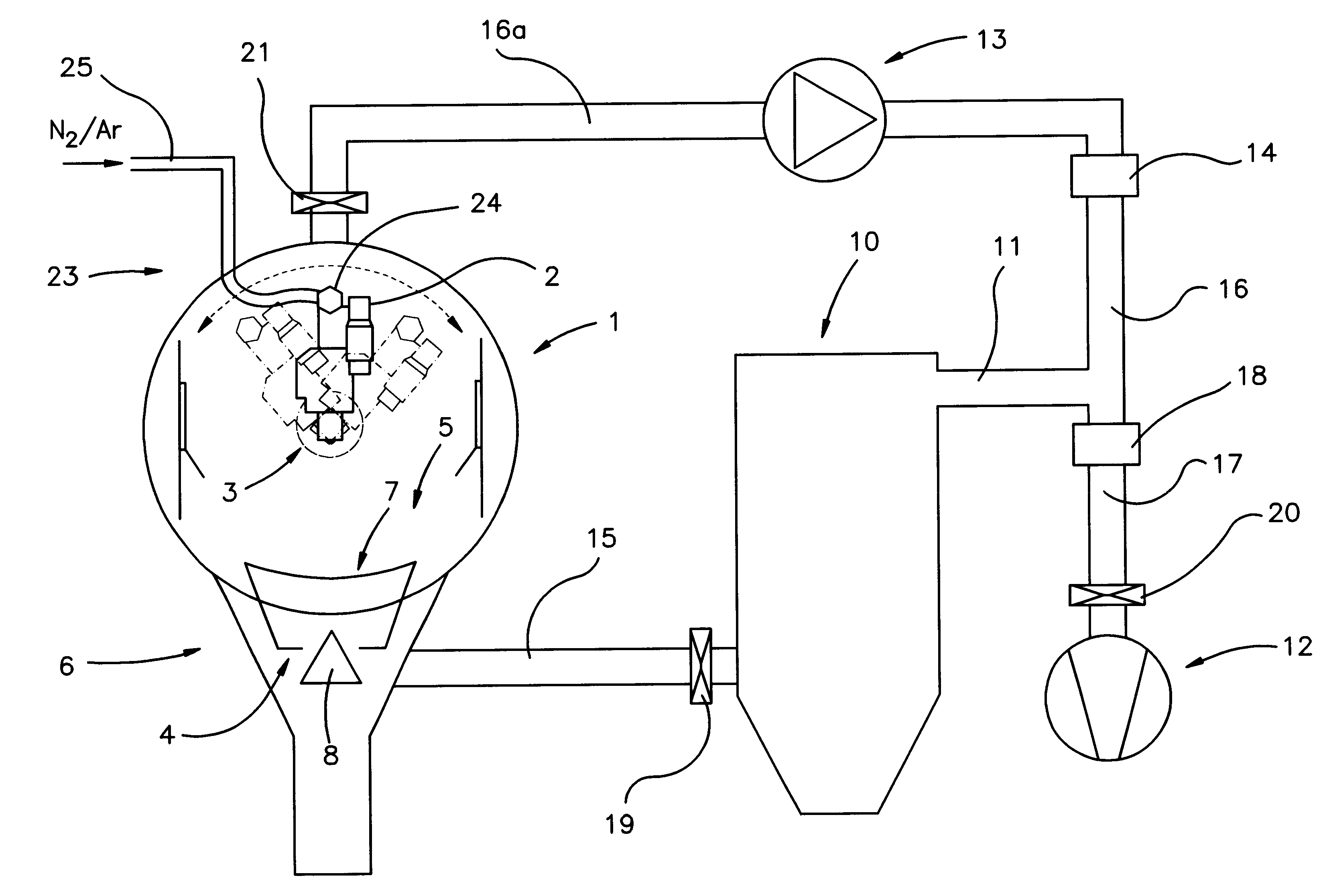
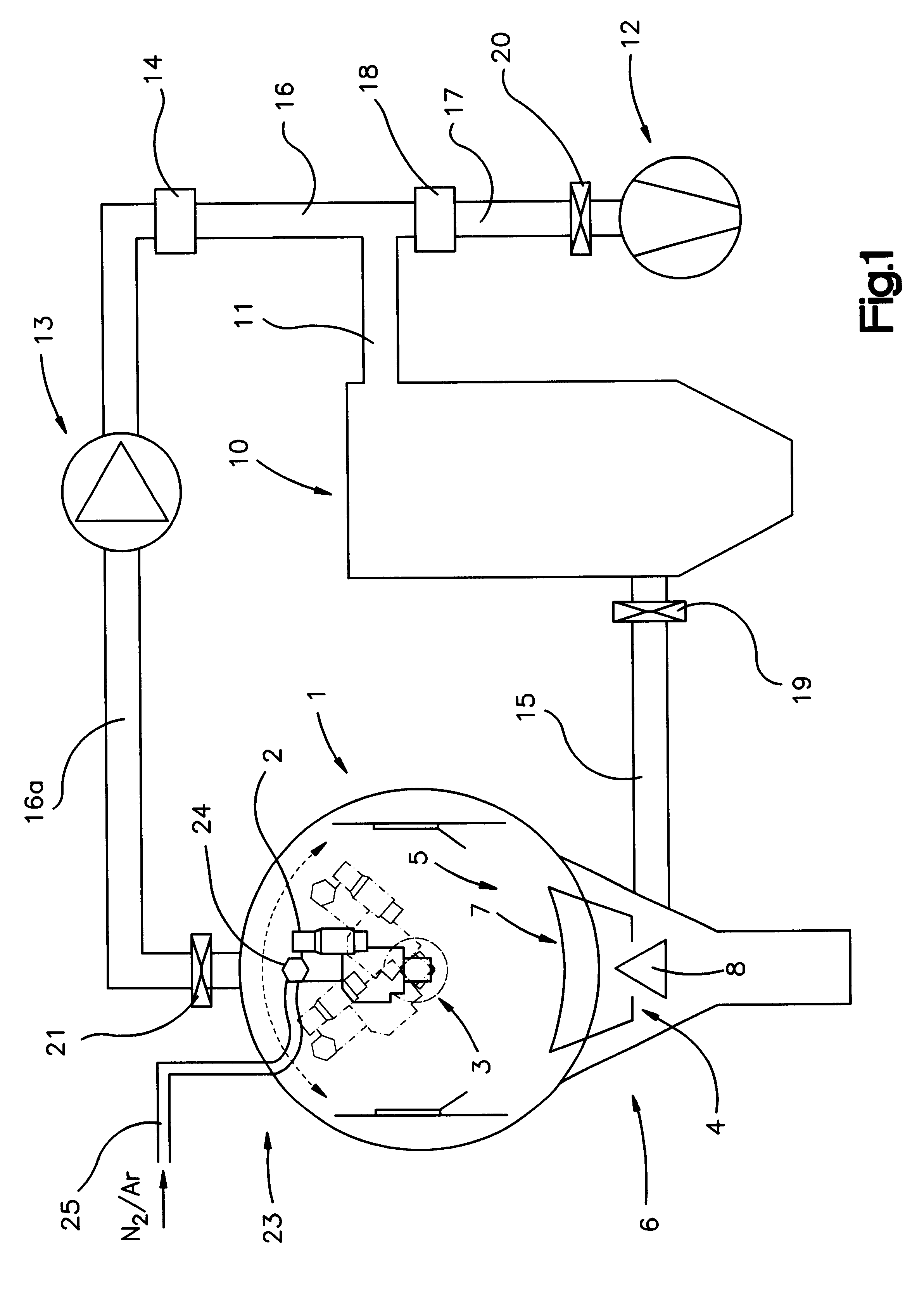
First, the general design of a plasma spraying apparatus including the assembly for controlling the gas flow according to the present invention will be further described with reference to FIG. 1. Since the basic principles of plasma spraying apparatuses comprising a treatment chamber and a plasma spraying device mounted in the interior thereof are well known to any person skilled in the art, only the elements and characteristics will be discussed in detail that are essential for the present invention.

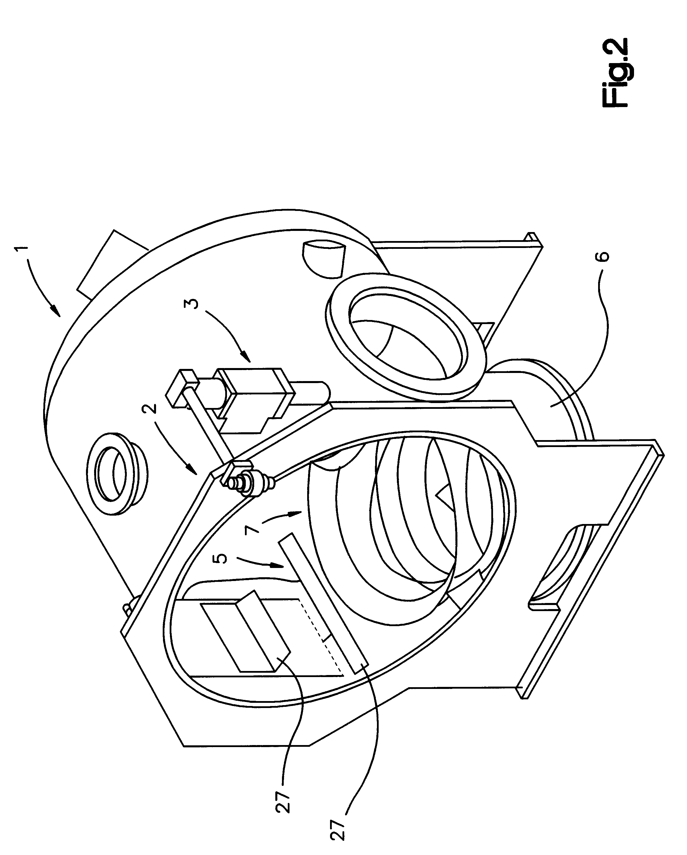
The plasma spraying apparatus comprises a treatment chamber 1 and a plasma spraying device 2 adapted to coat a substrate (not shown), located in the interior of the treatment chamber 1. Below the treatment chamber 1, a collecting shaft 6 is provided. Moreover, a deflecting device 5, a filter member 10 for removing coarse particles, two filter members 14, 18 for removing fine particles, a vacuum pump 12, a circulation blower 13 as well as a pneumatic cleaning device 23 are illustrated in...


PUM

PropertyMeasurementUnit
subatmospheric pressureaaaaaaaaaa
conical shapeaaaaaaaaaa
shapeaaaaaaaaaa

Abstract

A plasma spraying assembly comprising a treatment chamber and a plasma spraying device located in the interior thereof is disclosed that further comprises an assembly for controlling the gas flow in the interior of the treatment chamber. In order to prevent a gas flow in the interior of the treatment chamber that whirls deposits to be created, a deflection device is provided that is located at least partially in the interior of the treatment chamber. Vertically below the treatment chamber, a collecting shaft is located. In the region between the treatment chamber and the collecting shaft, there is provided a basic element comprising baffle members, but leaving open a passage between the treatment chamber and the collecting shaft. In the interior of the collecting shaft, a deflection element is located having essentially conical shape and towering into the passage of the basic element. The collecting shaft is in operative connection with the suction side of a blower and with a vacuum pump.

Description

The present invention refers to an assembly for controlling the gas flow in a plasma spraying apparatus that comprises a treatment chamber and a plasma spraying device located in the interior of the treatment chamber.For plasma coating of substrates, in most cases a plasma spraying apparatus is used that comprises a treatment chamber in the interior of which an atmosphere is created that is most suitable for a particular coating operation. Thereby, a plasma jet is generated by means of a plasmatron. In that plasma jet, the coating material to be applied to the surface of a substrate is molten. The plasma jet can reach a very high velocity, up to the ultrasonic region. However, in the interior of the treatment chamber, a gas flow is created during the operation of the plasmatron, particularly caused by the plasma jet. Such a gas flow can have a negative influence on the purity of the surface of the substrate as well as on the quality of the coating applied to the surface of the subst...

Claims


Application Information

Patent Timeline
Patent Type & Authority Patents(United States)
IPC IPC(8): C23C4/12C23C4/134C23C4/137
CPCC23C4/128C23C4/127C23C4/134C23C4/137
Inventor KELLER, SILVANO
Owner SULZER METRO AG
Why Eureka
Try Eureka