
Bolt positioning structure

A bolt positioning and bolt technology, applied in the directions of bolts, screws, nuts, etc., can solve the problems of inability to complete the assembly content, detachment, bolt positioning, etc., and achieve the effect of simple structure, high structural stability and convenient manufacturing.

Inactive Publication Date: 2016-01-13
AECC SHENYANG ENGINE RES INST
View PDF6 Cites 3 Cited by
  • Summary
  • Abstract
  • Description
  • Claims
  • Application Information

AI Technical Summary

Problems solved by technology

The bolt penetrates the mounting edge of the first part from bottom to top, and the head of the bolt is placed below the mounting edge of the first part. Due to the limited space, the bolt cannot be positioned by hand or tools, resulting in the bolt due to gravity and other reasons. Detached from the installation edge of the first part, the subsequent assembly content cannot be completed

Method used


Image

  • Bolt positioning structure
  • Bolt positioning structure

Examples


Embodiment 1

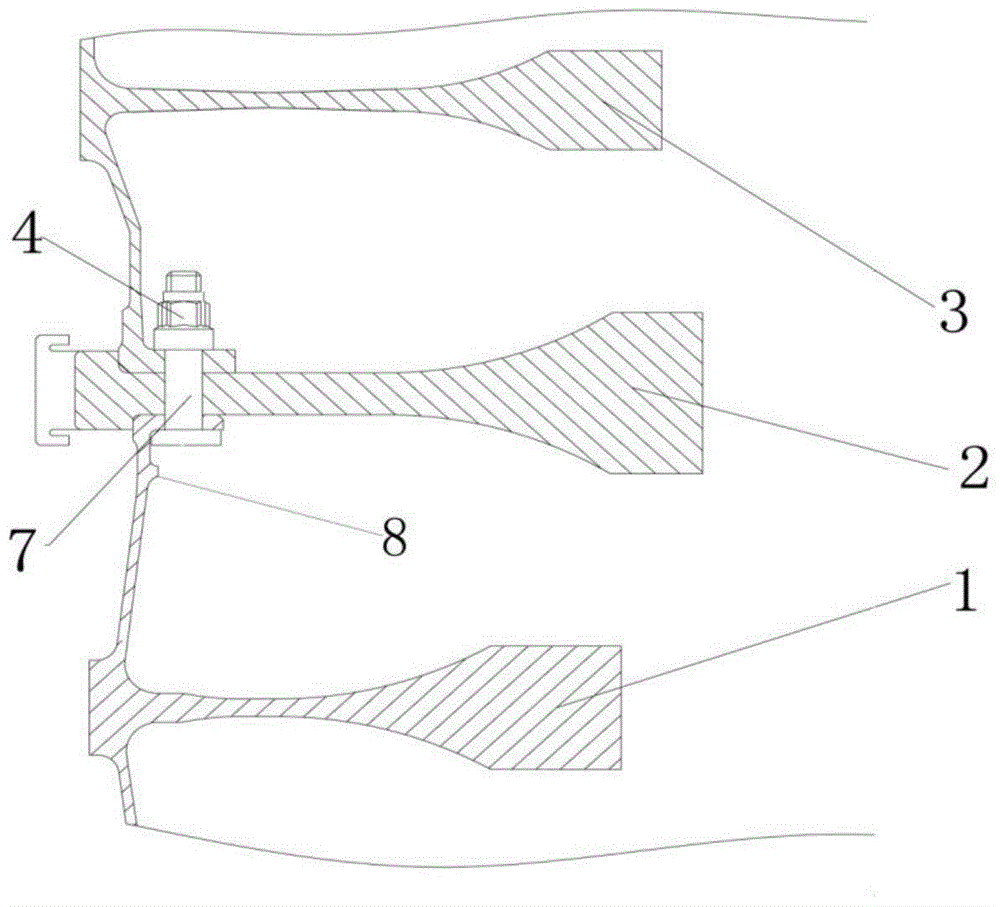
[0017] Such as figure 1 As shown, the bolt positioning structure provided by the present invention includes a first part 1, a bolt 7, and a nut 4. The bolt 7 passes through the installation edge of the first part 1, and cooperates with the nut 4 to connect the first part 1 with the nut 4. Other parts are fixedly connected, wherein a boss 8 is set on the inner wall of the first part 1, and the head of the bolt 7 is placed between the mounting edge of the first part 1 and the boss and overlapped on the boss 8 . Nut 4 is a self-locking nut. If it is inconvenient to use the self-locking nut during use,

[0018] The screw rod of the bolt 7 is composed of a polished rod part and a threaded rod part, wherein the polished rod part is arranged between the head of the bolt 7 and the threaded rod, and the length of the polished rod part is the installation side of the first part 1 and the installation side of other parts the sum of the thicknesses. The head of the bolt 7 is set to a ...

Embodiment 2

[0024] Referring to the above-mentioned embodiment 1, the difference lies in that this embodiment replaces the self-locking nut by the following scheme: a washer is arranged between the nut 4 and the other parts. The screw rod of the bolt 7 is provided with an anti-rotation groove, and a retaining ring is arranged in the anti-rotation groove, and the distance between the washer and the retaining ring is the same as the thickness of the nut. In this embodiment, the nut 4 can be either a self-locking nut or an ordinary nut.

[0025] The above two embodiments show that three parts are connected, but, according to the above embodiments, those skilled in the art can understand that the number of parts connected can be changed according to different actual situations, and can be two parts or more Component. The above-mentioned "other parts" refer to not only one part, but also multiple parts.

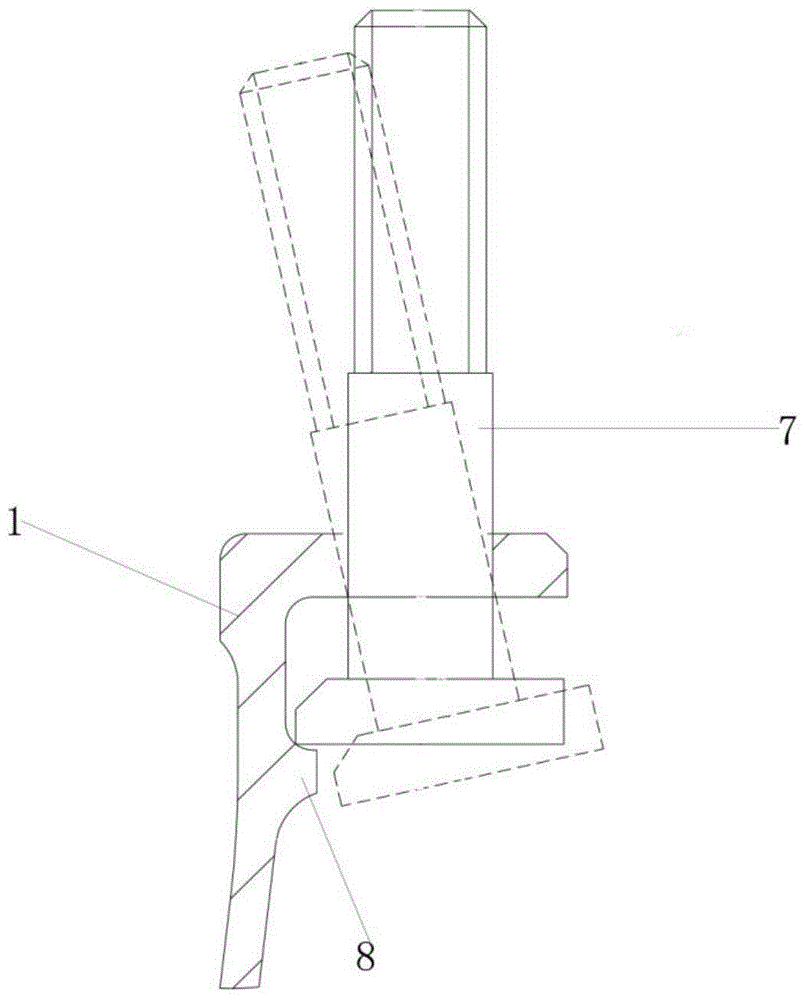
[0026] figure 2 Shown is the process of inserting the bolt 7 into the bolt hole on th...


PUM


Abstract

The invention discloses a bolt positioning structure and relates to the technical field of aircraft structure design. The bolt positioning structure is used for structure design of connectors of aircraft boxes and wheel disks of aircrafts. The head portion of a bolt (7) is of a D-shaped structure. A nut (4) is a self-locking nut. The inner wall of a first part (1) is provided with a boss (8). The head portion of the bolt (7) is placed between the installation edge of the first part (1) and the boss (8) and connected with the boss (8) in an overlap mode. The first part (1) is connected with the other parts smoothly by limiting the axial motion of the bolt (7). The bolt positioning structure is simple in structure, convenient to produce, high in structure stability, safe, reliable and convenient to operate. The defect that the bolt can not be limited due to insufficient space in the bolt connecting positions of the aircraft boxes, the wheel disks, etc., is avoided.

Description

technical field [0001] The invention relates to the technical field of aircraft structure design, in particular to a bolt positioning structure. Background technique [0002] In the prior art, in the assembly process of the casing, the wheel, etc., the general process of using bolts to vertically connect multiple structural parts is as follows: the bolts are installed on the mounting edge of the first part from bottom to top in advance, and then the second The first part is assembled from top to bottom, so that its mounting edge passes through the bolt shank and the first part is assembled, and the third part is also assembled in place, and so on, and finally the nut is assembled to connect multiple parts. The bolt penetrates the mounting edge of the first part from bottom to top, and the head of the bolt is placed below the mounting edge of the first part. Due to the limited space, the bolt cannot be positioned by hand or tools, resulting in the bolt due to gravity and othe...

Claims


Application Information

Patent Timeline
Patent Type & Authority Applications(China)
IPC IPC(8): F16B41/00F16B35/00
Inventor 王华韩方军印雪梅刘冬
Owner AECC SHENYANG ENGINE RES INST
Features
  • Generate Ideas
  • Intellectual Property
  • Life Sciences
  • Materials
  • Tech Scout
  • Unparalleled Data Quality
  • Higher Quality Content
  • 60% Fewer Hallucinations
Learn More