Energy-saving controller of electromagnetic valve

A solenoid valve and controller technology, applied in valve details, valve operation/release devices, valve devices, etc., can solve problems such as energy waste and power consumption, and achieve the effect of extending service life, protection and energy saving.

Inactive Publication Date: 2016-01-13
张虹
View PDF5 Cites 0 Cited by
  • Summary
  • Abstract
  • Description
  • Claims
  • Application Information

AI Technical Summary

Problems solved by technology

Although this solves the problem of coil heating, it will consume electric energy in vain, which greatly wastes energy.

Method used


Image

  • Energy-saving controller of electromagnetic valve

Examples


Embodiment Construction

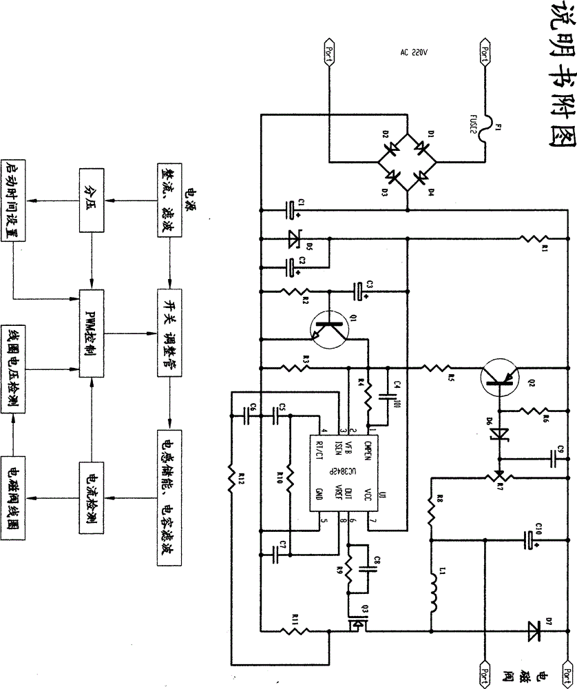
[0015] As shown in the figure, with diode D 1 -D 4 The input voltage is bridge rectified, and then through the capacitor C 1 The input peak DC voltage obtained after filtering (to ensure sufficient electromagnetic suction in the early stage of the solenoid valve closing), the power supply is controlled by the resistor R 1 shunt, Zener diode D 5 regulator, capacitor C 2 After filtering, it is used by PWM chip UC3842 and start-up delay circuit. Capacitance C 3 , resistor R 2 , Transistor Q 3 Form a start-up delay circuit to ensure that the solenoid valve has sufficient electromagnetic suction when it starts. After the set delay time, the PWM chip UC3842 automatically enters the energy-saving state (according to the model of the solenoid valve, adjust R 7 , so that the voltage across the solenoid valve coil can be stabilized at an appropriate value). Change the resistor R 10 and capacitance C 5 , can change the oscillation frequency of the PWM chip UC3842. Adjust resis...


PUM


Abstract

Disclosed is an energy-saving controller of an electromagnetic valve. A power source of an electromagnetic coil is controlled, large operational current (rated operational current) is used at the moment of power-on operation (pull-in) of the electromagnetic coil; small operational current (40%-70% of rated operational current) is used after power-on operation (after pull-in) of the electromagnetic coil; therefore, idle work is greatly reduced, and the heating amount of the electromagnetic coil is greatly decreased. Accordingly, the energy is saved, meanwhile, the electromagnetic coil is protected, and damage to the electromagnetic coil and equipment can be greatly reduced.

Description

technical field [0001] The invention patent relates to electrical technology and electrical control technology. Background technique [0002] With the development of industrial automation, solenoid valves are widely used. What follows is the problem of energy loss of the solenoid valve and equipment failure caused by the self-heating of the solenoid coil of the solenoid valve. According to the electromagnetic attraction expression (Fx=-5.1×[u 0 (IW) 2 S / δ]) in the formula: the magnetic permeability of Uo_air; [0003] IW_excitation ampere-turns; [0004] S_ The area of ​​the armature surface that determines the magnetic permeability and electromagnetic attraction (cm 2 ); [0005] δ_The length of the air gap is the distance between the magnetic poles in centimeters; [0006] The negative sign in the formula indicates that the electromagnetic attraction force Fx increases with the decrease of the air gap δ. [0007] It can be seen that the structure adopted by the exi...

Claims


Application Information

Patent Timeline
Patent Type & Authority Applications(China)
IPC IPC(8): F16K31/06
Inventor 张虹
Owner 张虹
Why Eureka
Try Eureka