
A light beam directivity debugging system and method

A technology of beam pointing and debugging system, which is applied in the direction of optical instrument testing, machine/structural component testing, measuring devices, etc. It can solve the problems of large fluctuations in debugging quality, unsuitable for batch debugging of workpieces, and low debugging accuracy. Good consistency of results, high debugging efficiency, and standardized debugging process

Inactive Publication Date: 2017-10-10
BEIJING GK LASER TECH
View PDF8 Cites 0 Cited by
  • Summary
  • Abstract
  • Description
  • Claims
  • Application Information

AI Technical Summary

Problems solved by technology

[0005] 1. The debugging accuracy is low, the process control is more random, basically depends on the working status of the debugger, and the debugging quality fluctuates greatly;
[0006] 2. Not suitable for batch debugging of workpieces;
[0007] 3. It is not convenient to design matching debugging tooling for standardized production;
[0008] 4. It is not conducive to the basic and basic pre-adjustment control of the light output direction of each mirror group before assembly and debugging of the relevant mirror groups in the entire laser system or before the optical path debugging of the final assembly system, so as to eliminate most of the Deviation of light directionality, which has a great impact on improving the quality of laser light output

Method used


Image

  • A light beam directivity debugging system and method
  • A light beam directivity debugging system and method

Examples


Embodiment Construction

[0033] In order to describe the technical content, structural features, achieved goals and effects of the present invention in detail, the following will be described in detail in conjunction with the embodiments and accompanying drawings.

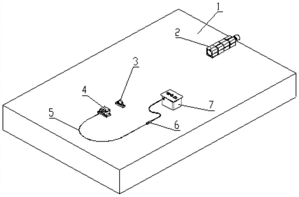
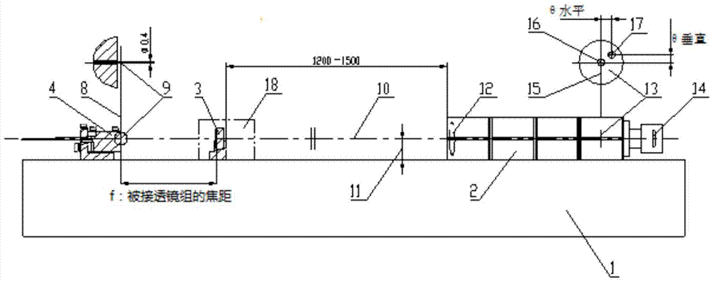
[0034] In one embodiment, the present invention provides a light beam directivity adjustment system, including a reference platform, a square tube front mirror, an adjusted lens group, a standard cursor group, a conductive optical fiber, a red light source, and a light source control box.

[0035] The square tube front mirror, adjusted lens group and standard cursor group are set on the reference platform and arranged in sequence along the optical path.

[0036] The red light source and the light source control box constitute a controllable light source and are transmitted to the indicating end face of the standard cursor group through the conducting fiber; the conducting fiber, the red light source and the light source control box are arra...


PUM


Abstract

The invention provides a light beam directivity debugging system, which includes a reference platform, a square tube front mirror, an adjusted lens group, a standard cursor group, a conductive optical fiber, a red light source, and a light source control box; The lens group and the standard cursor group are sequentially arranged on the reference platform along the optical path; the red light source and the light source control box form a controllable light source and are transmitted to the indicating end face of the standard cursor group through the conduction fiber; the conduction fiber, the red light source and the light source control box are set On the reference platform; the collimation axis of the square tube front mirror and the standard cursor group are constructed as a reference axis, and the light-emitting end face of the standard cursor group is used as an indicator cursor to guide the adjusted lens group to indicate the light-emitting point of the lens for debugging. The light beam directivity debugging system of the present invention uses the collimation axis of the front mirror of the square tube and the standard cursor group to establish a reference axis, and uses the light-emitting end face of the standard cursor group as an indicator cursor to indicate the light output direction of the lens through the imaging position of the adjusted lens. , so that precise debugging can be performed.

Description

【Technical field】 [0001] The invention relates to the technical field of light beam debugging, in particular to a system and method for precise debugging of beam directivity. 【Background technique】 [0002] In the laser industry, the common problems and defects of the currently commonly used adjustment methods for the light output direction of the positive lens or the positive lens group are as follows: [0003] The common method of debugging is generally to use a helium-neon laser light source to give a thin beam of light through the aperture diaphragm and visually observe the alignment of the light to the target, so as to roughly debug the light directivity of the lens. Therefore, the debugging accuracy is generally low, and generally the specific accuracy control range cannot be guaranteed. [0004] The disadvantages of this method are: [0005] 1. The debugging accuracy is low, the process control is more random, basically depends on the working status of the debugger,...

Claims


Application Information

Patent Timeline
Patent Type & Authority Patents(China)
IPC IPC(8): G01M11/04
Inventor 王家赞胡列科张国新周密
Owner BEIJING GK LASER TECH
Learn More