
Motorized spindle structure optimization method based on parametric finite element model

An optimization method, the technology of the electric spindle, applied in the direction of electric digital data processing, special data processing applications, instruments, etc., can solve the problem of not considering high rigidity and light weight at the same time, not being able to optimize the structure of the electric spindle, and not being able to describe the actual situation of the spindle well and other problems, to achieve the effect of accurate model and obvious optimization effect

Active Publication Date: 2016-01-13
无锡鸣山机电科技有限公司
View PDF3 Cites 13 Cited by
  • Summary
  • Abstract
  • Description
  • Claims
  • Application Information

AI Technical Summary

Problems solved by technology

Looking at the existing literature, regarding the research on the optimization design of electric spindles, the optimization models established in some literatures are too simplified and cannot describe the actual situation of the spindle well; One goal, and most of the optimized design variables are the bearing position, and rarely consider the diameter of the main shaft bearing, the span of the front and rear support bearings, and the overhang of the main shaft.
Therefore, it is not possible to effectively optimize the structure of the electric spindle

Method used


Image

  • Motorized spindle structure optimization method based on parametric finite element model
  • Motorized spindle structure optimization method based on parametric finite element model
  • Motorized spindle structure optimization method based on parametric finite element model

Examples


Embodiment 1

[0048] refer to figure 2, Optimal design of U25-215446 milling electric spindle, which is used for high-speed milling of CNC machine tools, and can be used for semi-finishing and finishing. Specifically follow the steps below to optimize the motorized spindle:

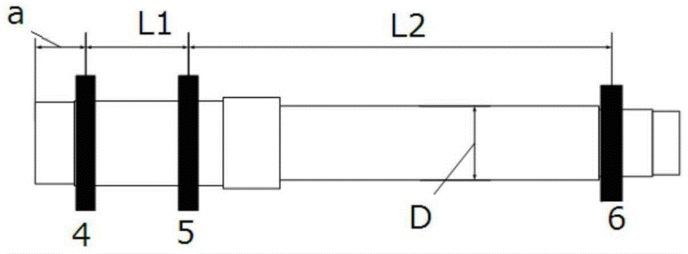
[0049] First, according to the object to be optimized, the optimized design variables and optimization objectives are defined in advance. Depend on figure 2 It can be seen that the electric spindle is composed of three bearings (respectively image 3 4, 5, 6) in the support. The front end is installed by a pair of angular contact ball bearings back to back, and there is a certain span between the two bearings; the rear end is supported by a floating displacement bearing to bear radial load. When optimizing the structure, refer to image 3 , select the main shaft overhang a, the front end bearing span L 1 , Back end bearing span L 2 And the outer diameter D of the rear end is the design variable, and the optimi...

Embodiment 2

[0091] refer to Figure 4 , an optimized design of a large-scale high-precision CNC form grinding electromechanical spindle. This electric spindle is used in CNC profile gear grinding machine for precision machining of large gears. Specifically follow the steps below to optimize the motorized spindle:

[0092] First, according to the object to be optimized, the optimized design variables and optimization objectives are defined in advance. From Figure 4 It can be seen that the front end of the electric spindle consists of 4 angular contact ball bearings installed back to back in pairs (corresponding to Figure 5 Combination bearings 4', 5'); the rear end is supported by two angular contact ball bearings to form a pair of back-to-back installation (corresponding Figure 5 Combined bearing 6'). refer to Figure 5 , when the structure is optimized, select the main shaft overhang a, the front end bearing span L 1 , Back end bearing span L 2 , front end shaft diameter D 1 ...


PUM


Abstract

The invention discloses a motorized spindle structure optimization method based on parametric finite element model. The method is characterized by comprising the following steps of: according to a to-be-optimized motorized spindle, initially defining a design variable and an optimization goal of an optimization problem; 2) taking the design variable as a variable parameter, and establishing a motorized spindle parametric finite element model; 3) according to a motorized spindle design principle and related theories, determining value range of the design variable and determining a state variable, establishing a constraint condition, and then establishing an objective function; 4) selecting an intelligent optimization algorithm to perform optimization solving, and obtaining an optimization result. The method optimization based on the motorized spindle parametric finite element model, nonlinear bearing stiffness is considered, the established model is more close to practice, the model is flexible, the optimization effect is good, and thus, the method is particularly suitable for dual-goal optimization of high stiffness and light weight of the motorized spindle. The method can effectively improve stiffness of the motorized spindle and reduce mass of the motorized spindle, and provides effective guidance for design of the motorized spindle.

Description

technical field [0001] The invention relates to mechanical structure design, in particular to a method for optimal design of structural parameters of an electric spindle of a machine tool. Background technique [0002] The electric spindle is the core component of high-speed and high-precision CNC machine tools. It is a spindle system that integrates multiple technical units. Due to its high speed and high precision, the high-speed electric spindle can greatly improve the machining efficiency of machine tools and greatly improve the machining accuracy. The characteristics of the electric spindle itself directly affect the processing performance of the machine tool. Whether the design of the electric spindle is reasonable or not affects the performance of the spindle fundamentally, so it is particularly important to optimize the structure of the electric spindle. [0003] A lot of research has been carried out on the optimal design of machine tool spindles at home and abroa...

Claims


Application Information

Patent Timeline
IPC IPC(8): G06F17/50
Inventor 曹宏瑞李笔剑蔡俊琼樊利军郭召
Owner 无锡鸣山机电科技有限公司
Learn More