
Motor stator slot portion insulation structure

An insulation structure and motor stator technology, applied in the shape/style/structure of winding insulation, electrical components, electromechanical devices, etc., can solve the high insulation performance requirements of the stator slot, it is difficult to meet the operation requirements of the unit, and the stator slot is easy to appear Corona and other problems, to achieve the effect of increasing the sealing and insulation effect, saving resources, and good anti-corona effect

Active Publication Date: 2016-01-13
SICHUAN DONGFENG ELECTRIC MACHINARY WORKS CO LTD
View PDF4 Cites 2 Cited by
  • Summary
  • Abstract
  • Description
  • Claims
  • Application Information

AI Technical Summary

Problems solved by technology

For conventional units operating in high-altitude areas, due to the thin air, corona is prone to appear in the stator slot when the unit is running, which will cause problems such as electrical corrosion, chemical corrosion, and local high temperature, resulting in accelerated aging of wire rod insulation, damage to the unit, and shorten the unit. Operating life
At high altitudes, accidents of damage to the whole unit due to improper anti-halo treatment often occur
Especially when the altitude of the power station is above 3000m, the normal operation of the unit has higher requirements on the insulation performance of the stator slot, and the conventional stator slot structure is difficult to meet the operating requirements of the unit in a complex environment, and the stator slot must be specially treated
In addition, the insulating materials currently used in many motor units in China rely on foreign imports, which are costly and do not take advantage of my country's economic security. From the perspective of the country's long-term development, core technical issues must rely on independent research and development and innovation

Method used


Image

  • Motor stator slot portion insulation structure

Examples


Embodiment Construction

[0017] The present invention will be further described below in conjunction with the accompanying drawings, but the protection scope of the present invention is not limited to the following description.

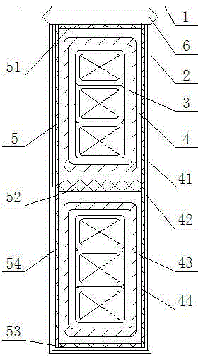
[0018] Such as figure 1 As shown, a motor stator slot insulation structure, which includes a stator core 1, a stator slot 2 is arranged on the stator iron core 1, a coil 3 is arranged in the stator slot 2, and a slot wedge 6 is arranged at the opening of the stator slot 2 , Slot wedge 6 adopts F-level two-way extraction wedge or H-level two-way extraction wedge. The wedge has high anti-split strength and regular cavity size, which can well meet the assembly requirements, and has little waste and saves resources. Usually, it is used 3240 or 3248 laminate processing.

[0019] A slot insulation structure 4 and a coil fixing structure 5 are arranged between the coil 3 and the stator slot 2. The slot insulation structure 4 includes an insulating glue layer 41, a low-resistance pa...


PUM


Abstract

The invention relates to a motor stator slot portion insulation structure. The structure comprises a stator core (1), the stator core (1) is provided with a stator slot (2), a coil (3) is disposed in the stator slot (2), a slot insulation structure (4) and a coil fixing structure (5) are disposed between the coil (3) and the stator slot (2), the slot insulation structure (4) comprises an insulation glue layer (41), a low-resistance paint layer (42),a rubber layer (43) and low-resistance cloth (44), and fixing materials used in the coil fixing structure (5) are 3241 semiconductor cushion strip. A practical application shows that a motor set adopting the stator slot portion structure runs well in a high-altitude area, set discharging, burnout and other accidents do not occur, set running safety can be effectively guaranteed, and the service life of the set is prolonged; and the whole insulation structure adopts homemade materials, economic cost is low, independent research, development and innovation of science and technology in our county are facilitated, and dependency and instability of imported foreign materials are reduced.

Description

technical field [0001] The invention relates to the technical field of motor manufacturing, in particular to an insulation structure for a slot portion of a motor stator. Background technique [0002] With the development of the national power industry, there are more and more generating sets in high altitude areas. For conventional units operating in high-altitude areas, due to the thin air, corona is prone to appear in the stator slot when the unit is running, which will cause problems such as electrical corrosion, chemical corrosion, and local high temperature, resulting in accelerated aging of wire rod insulation, damage to the unit, and shorten the unit. operating life. At high altitudes, accidents of damage to the whole unit due to improper anti-halo treatment of the unit occur from time to time. Especially when the altitude of the power station is above 3000m, the normal operation of the unit has higher requirements on the insulation performance of the stator slot. ...

Claims


Application Information

Patent Timeline
Patent Type & Authority Applications(China)
IPC IPC(8): H02K3/34H02K3/40H02K3/487
Inventor 魏雄强李泽端
Owner SICHUAN DONGFENG ELECTRIC MACHINARY WORKS CO LTD
Learn More