Power conversion device, motor drive control device equipped with power conversion device, compressor and blower equipped with motor drive control device, and air conditioner equipped with compressor or blower

A technology of power conversion device and motor, which is applied in the direction of AC motor control, high-efficiency power electronic conversion, output power conversion device, etc.

Active Publication Date: 2016-01-13
MITSUBISHI ELECTRIC CORP
View PDF7 Cites 6 Cited by
  • Summary
  • Abstract
  • Description
  • Claims
  • Application Information

AI Technical Summary

Problems solved by technology

[0002] In the past, in order to suppress failures caused by harmonic components contained in power supply current, international restrictions were set on electronic equipment that generates harmonic currents

Method used


Image

  • Power conversion device, motor drive control device equipped with power conversion device, compressor and blower equipped with motor drive control device, and air conditioner equipped with compressor or blower
  • Power conversion device, motor drive control device equipped with power conversion device, compressor and blower equipped with motor drive control device, and air conditioner equipped with compressor or blower
  • Power conversion device, motor drive control device equipped with power conversion device, compressor and blower equipped with motor drive control device, and air conditioner equipped with compressor or blower

Examples


Embodiment approach 1

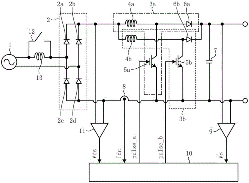
[0055] figure 1 It is a figure which shows the structural example of the power conversion apparatus concerning this embodiment. Such as figure 1 As shown, the power conversion device has a single-phase rectifier 2, chopper circuit parts 3a, 3b, smoothing capacitor 7, bus current detection part 8, bus voltage detection part 9, switch control part 10, rectified voltage detection part 11, AC switch 12 and AC reactor 13.

[0056] The single-phase rectifier (hereinafter simply referred to as "rectifier") 2 is constituted by connecting four rectifier diodes 2a to 2d in bridge form, and rectifies the AC voltage of single-phase AC power supply (hereinafter simply referred to as "AC power supply") 1 . The chopper circuit unit 3a is composed of a reactor 4a, a switching element 5a, and a backflow prevention element 6a. The chopper circuit unit 3b is composed of a reactor 4b, a switching element 5b, and a backflow prevention element 6b. Such as figure 1 As shown, the chopper circui...

Embodiment approach 2

[0110] Figure 7 It is a figure which shows the structural example of the power conversion apparatus concerning this embodiment. Its structure in embodiment 1 (referring to figure 1 ) has added a DC switch 14. The DC switch 14 is arranged in parallel with the chopper circuit units 3a, 3b.

[0111] The DC switch 14 is a b-contact electromagnetic switch whose contacts are in an open state when excited. The DC switch 14 has its contacts turned on under intermediate operating conditions, and is energized during current control based on the switching operations of switching elements 5a and 5b under output conditions higher than the intermediate operating conditions, and is in a contact-off state. Other structures and operations are the same as those in Embodiment 1.

[0112] Accordingly, in the power conversion device, the rated loss of the backflow prevention elements 6a, 6b and the copper loss of the reactors 4a, 4b can be reduced by bypassing in the intermediate operating co...

Embodiment approach 3

[0116] Figure 8 It is a figure which shows the structural example of the power conversion apparatus concerning this embodiment. It is from the structure of Embodiment 1 (refer to figure 1 ), the AC switch 12 and the AC reactor 13 are deleted, and the AC reactor 15, the AC switch 16, the rectifier 17, and the AC switch 18 are added. The AC reactor 15, the AC switch 16, and the rectifier 17 are connected in series, and are arranged in parallel with the rectifier 2 as the first rectifier and the chopper circuit units 3a and 3b. The rectifier 17 as the second rectifier has the same structure as the rectifier 2 as the first rectifier. In addition, an AC switch 18 is arranged between the AC power source 1 and the rectifier 2 .

[0117] The AC switch 16 as the first AC switch is a b-contact type electromagnetic switch that is in a contact-off state when excited. In addition, the AC switch 18 which is a 2nd AC switch is an a-contact electromagnetic switch which becomes a contact-...


PUM


Abstract

A power conversion device is configured by parallel connecting of chopper circuits (3a, 3b) which each include a reactor (4a, 4b), a switching element (5a, 5b), and a backflow prevention element (6a, 6b) and chop and boost the output of a rectifier (2) that rectifies the AC voltage from an AC power source (1), the power conversion device comprising: an AC switch (12) arranged closer to the AC power source (1) than the chopper circuits (3a, 3b); an AC reactor (13) arranged closer to the AC power source (1) than the chopper circuits (3a, 3b) and connected in parallel with the AC switch (12); and a switching control unit (10) for controlling the operation of the switching elements (5a, 5b) and the AC switch (12). When the contacts of the AC switch (12) are open, the switching control unit (10) suspends the switching of the switching elements (5a, 5b).

Description

technical field [0001] The present invention relates to a power conversion device, a motor drive control device having the power conversion device, a compressor and a blower having the motor drive control device, and an air conditioner having the compressor or the blower. Background technique [0002] Conventionally, in order to suppress failures caused by harmonic components contained in power supply current, international restrictions have been set on electronic devices that generate harmonic currents. In order to comply with this restriction, the following countermeasures are taken: use the converter to short-circuit the power supply by AC or DC chopping, and suppress the harmonic current contained in the power supply current. [0003] Among converters that perform DC chopping, there is an interleaved converter in which a plurality of chopper circuit sections are connected in parallel and switched at different switching phases. In , the harmonic current is suppressed by ...

Claims


Application Information

Patent Timeline
Patent Type & Authority Applications(China)
IPC IPC(8): H02M1/12H02M3/155
CPCH02M1/4225H02M3/1584H02M1/12H02M5/458H02M7/08H02M7/53871F24F11/85H02M7/06Y02B70/10H02M1/0048H02M3/1586H02P27/00
Inventor 山田伦雄下麦卓也筱本洋介鹿岛美津夫梅原成雄
Owner MITSUBISHI ELECTRIC CORP
Why Eureka
Try Eureka