Threshing device

A technology of threshing device and wallboard, which is applied in the direction of threshing equipment, application, agricultural machinery and implements, etc. It can solve the problems of blockage, excessive feeding of threshing device, etc., and achieve the effect of reducing grain loss

Inactive Publication Date: 2016-01-20
CHONGQING XINSHUI MACHINERY MFG
View PDF0 Cites 1 Cited by
  • Summary
  • Abstract
  • Description
  • Claims
  • Application Information

AI Technical Summary

Problems solved by technology

[0005] The present invention intends to provide a threshing device to solve the problem that the existing threshing device is easily blocked due to excessive feeding

Method used


Image

  • Threshing device
  • Threshing device

Examples


Embodiment Construction

[0022] The present invention will be described in further detail below by means of specific embodiments:

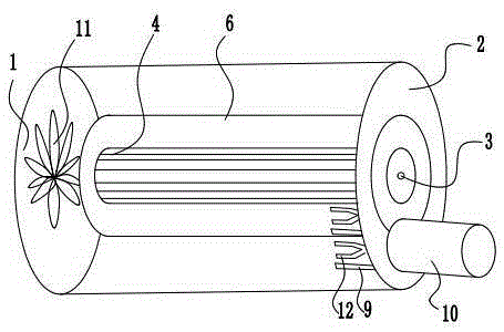
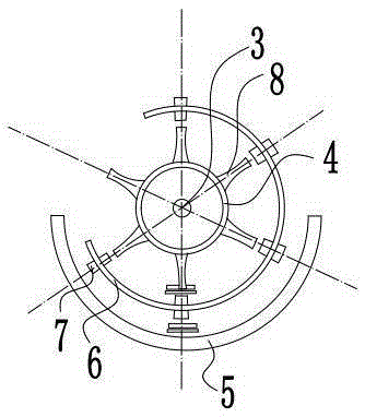
[0023] The reference signs in the accompanying drawings of the specification include: left wallboard 1, right wallboard 2, roller shaft 3, spiked roller 4, concave plate sieve 5, shell 6, protrusion 7, spiked teeth 8, collecting tank 9, miscellaneous Material pipe 10, fan 11, jaw 12.

[0024] as attached figure 1 And attached figure 2 Shown: a threshing device, including a left wall panel 1, a right wall panel 2 fixed on the harvester or the fuselage of the harvester, and a cleaning device arranged on the left wall panel 1 and the right wall panel 2, the left wall panel 1 and the right wall panel 2 is provided with a roller shaft 3, the outer surface of the roller shaft 3 is provided with a nail-toothed roller 4, a concave plate sieve 5 is arranged under the nail-toothed roller 4, and a sieve hole is arranged on the concave plate sieve 5; 5 is connected between the le...


PUM


Abstract

The invention relates to the field of agricultural harvesting machinery, and particularly discloses a threshing device which comprises a left wall plate, a right wall plate and cleaning facilities, wherein the left wall plate and the right wall plate are fixed on the main body of a harvesting machine or a reaping machine; the cleaning facilities are arranged on the left wall plate and the right wall plate; a drum shaft is arranged between the left wall plate and the right wall plate, and sleeved by a spike-tooth drum; a concave plate screen is arranged below the spike-tooth drum; screen holes are formed in the concave plate screen; the concave plate screen is connected between the left wall plate and the right wall plate, and totally covers the spike-tooth drum; the spike-tooth drum is sleeved by a housing; the housing is a hollow cylinder with openings formed in the side surface; radial bulges and leaks are formed on and in both the inner wall and the outer wall on the side surface of the housing; the housing is connected onto the drum shaft, and can rotate around the drum shaft together with the spike-tooth drum.

Description

technical field [0001] The invention relates to the field of agricultural harvesting machinery, and specifically discloses a threshing device. Background technique [0002] In an agricultural harvester or harvester, a threshing device is an essential structure. The threshing device is mainly used to separate sundries such as grain stalks from the grain. [0003] Existing threshing devices generally include a drum shaft, a spiked drum rotating around the rolling shaft, and a concave plate screen arranged below the spiked drum. During threshing, it mainly relies on the impact of the spikes on the spiked drum on the grain and the grinding effect of the spiked teeth on the spiked drum and the concave plate sieve on the grain to make the grain fall off and leak out from the holes on the concave plate sieve. [0004] However, because the feeding amount is too large, the grinding movement between the spiked drum and the concave plate sieve is difficult, and the relative movement ...

Claims


Application Information

Patent Timeline
Patent Type & Authority Applications(China)
IPC IPC(8): A01F7/02A01F12/22A01F12/44
Inventor 廖佳袁
Owner CHONGQING XINSHUI MACHINERY MFG
Why Eureka
Try Eureka