a soybean milk machine

A soymilk machine and machine head technology, which is applied in beverage preparation devices, household appliances, applications, etc., can solve the problems of reduced fun of soymilk drinks, hidden safety hazards, and easy pollution of the desktop, etc., and achieves convenient installation, compact installation structure, fine lifting degree of effect

Active Publication Date: 2018-02-09
HONGYANG HOME APPLIANCES
View PDF6 Cites 0 Cited by
  • Summary
  • Abstract
  • Description
  • Claims
  • Application Information

AI Technical Summary

Problems solved by technology

But at the same time, when the pulverizing blade twitches the liquid flow to circulate upward, the slurry sprayed from the diversion hole may splash, which is easy to burn the customer and poses a safety hazard
Moreover, the splashed slurry is also easy to contaminate the desktop, which reduces the enjoyment of customers making soybean milk drinks

Method used


Image

  • a soybean milk machine
  • a soybean milk machine
  • a soybean milk machine

Examples


Embodiment 1

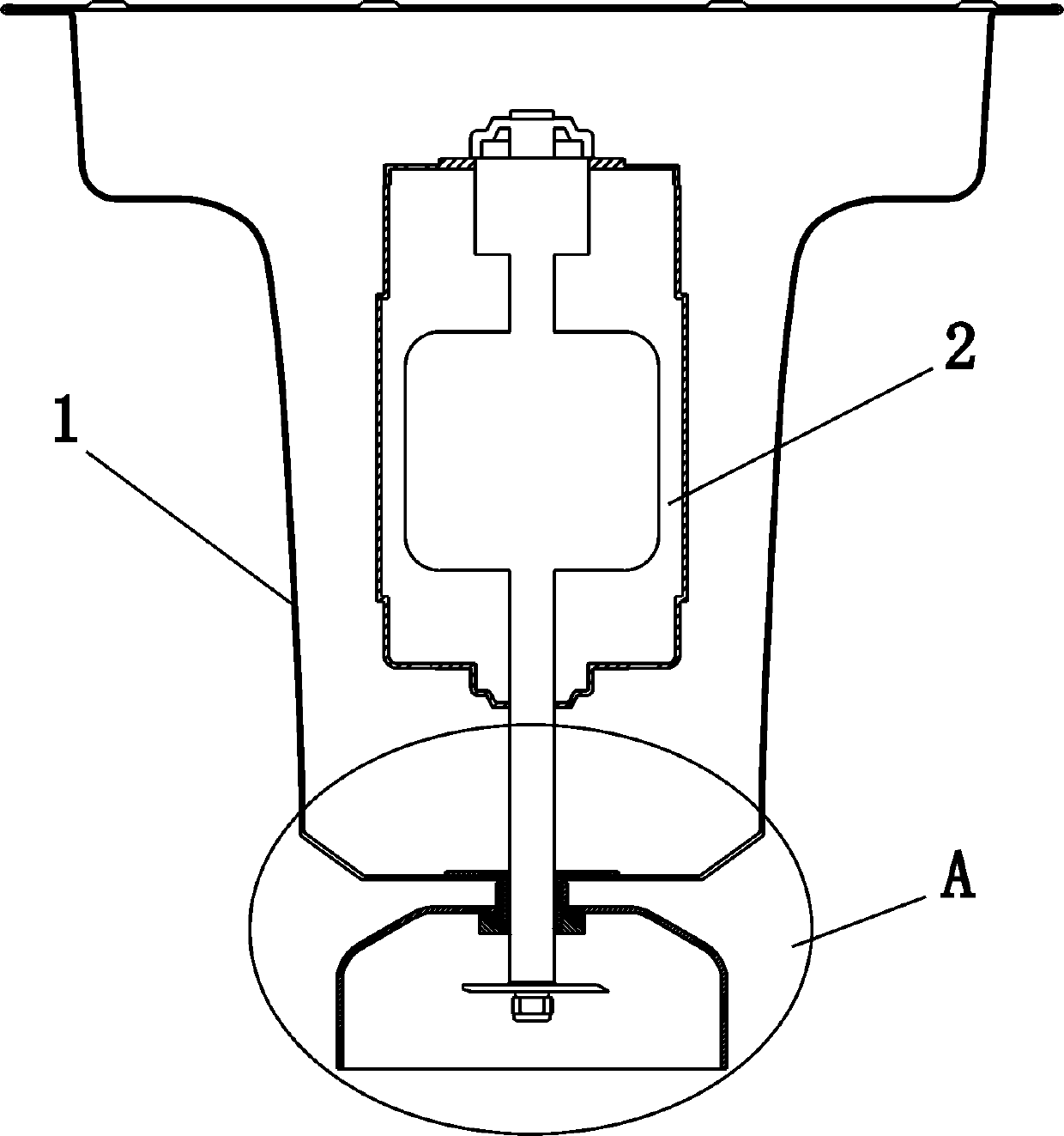
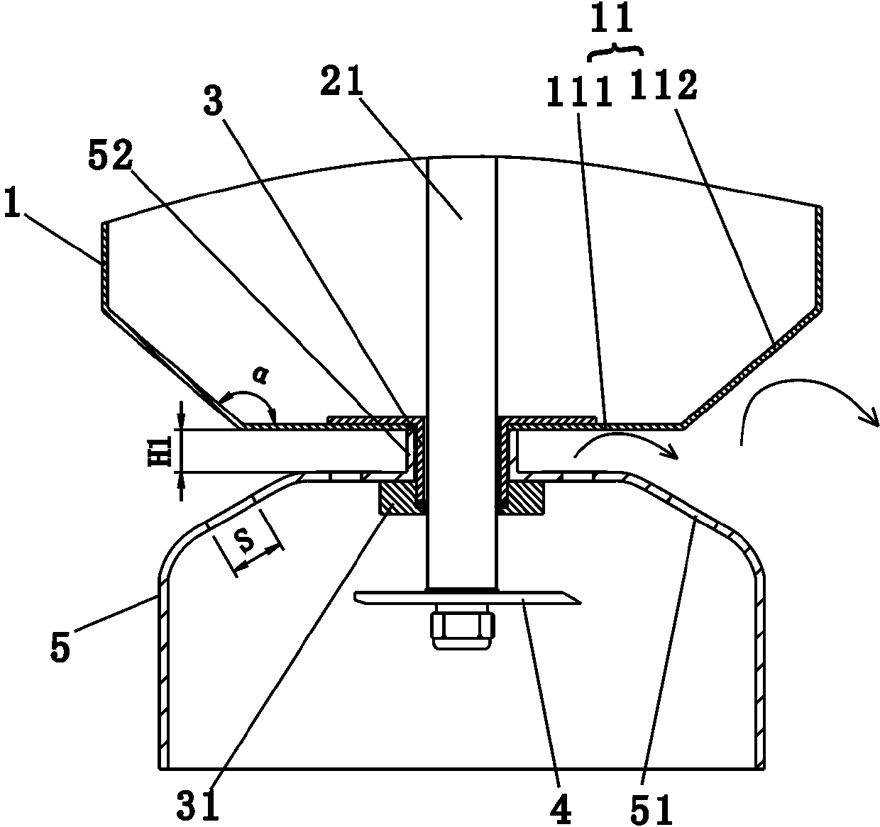
[0022] Such as figure 1 , figure 2 Shown is a schematic structural diagram of the first embodiment of the present invention. A soybean milk machine, comprising a machine head and a cup body (not shown in the figure), the machine head includes a machine head upper cover (not shown in the figure) and a machine head lower cover 1, the machine head lower cover 1 A motor 2 is provided, the bottom of the machine head lower cover 1 is provided with a connecting body 3 protruding downward, the end of the motor shaft 21 is equipped with a pulverizing blade 4, and the bottom of the connecting body 3 is provided with a shroud 5, so The pulverizing blade 4 is located in the shroud 5, and the shredder 5 is provided with a diversion hole 51 above the shredding blade 4, and the motor shaft 21 drives the pulverizing blade 4 to rotate and pump the liquid flow to be guided through the shroud 5. The hole 51 sprays to the outside of the guide cover 5, and the bottom of the lower cover 1 of the...

Embodiment 2

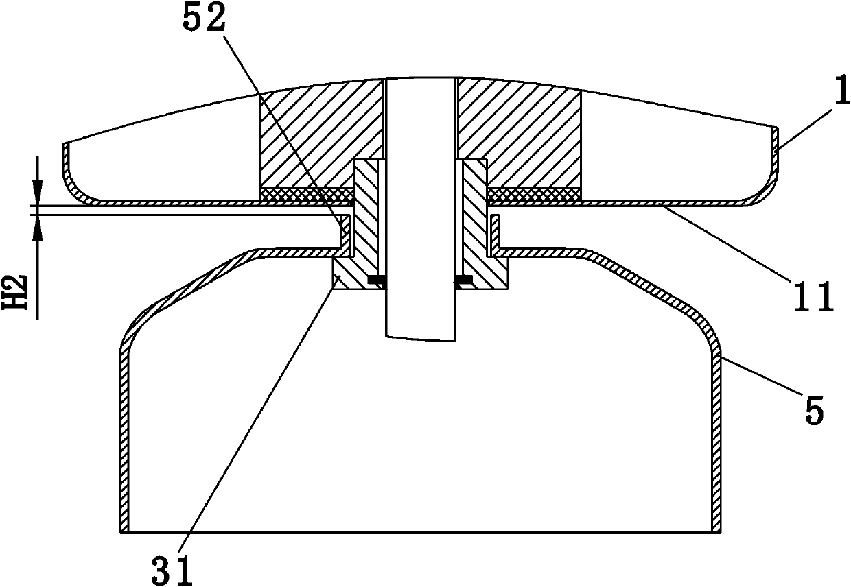
[0029] Such as image 3 Shown is a schematic structural diagram of the second embodiment of the present invention. The difference from Embodiment 1 is that in this embodiment, the spoiler surface 11 is the bottom outer plane of the lower head cover 1, and the air deflector 5 is movably installed between the lower head cover 1 and the convex ring 31. and the distance between the top of the sleeve part 52 and the bottom outer plane of the lower nose cover is H2. The movable installation of the wind deflector 5 is to guide the wind deflector to be positioned between the lower nose cover 1 and the convex ring 31. Circumferential rotation or axial movement.

[0030] In this embodiment, since the guide cover can rotate in the circumferential direction, the sleeve part and the connecting cylinder are in clearance fit, and during the pulping process, the movement of the guide cover will change the original trajectory of the liquid flow, thereby increasing The effect of turbulent flo...

Embodiment 3

[0032] Such as Figure 4 Shown is a schematic structural view of the third embodiment of the present invention. The difference between this embodiment and the above-mentioned embodiments is that in this embodiment, the connecting body 3 is a connecting bracket, the top of the connecting bracket is detachably connected to the lower cover 1 of the machine head, and the bottom is connected to the air guide cover 5 Shaped together.

[0033] It should be noted that, in this embodiment, the connecting bracket and the nozzle cover are integrally formed, and the connecting bracket and the lower cover of the machine head are detachable and fixed, which is beneficial to the cleaning of the nozzle cover and the machine head. Of course, the connecting bracket can also be integrated with the lower cover of the machine head, and the shroud and the connecting bracket are detachable and fixed structures. For this embodiment, the connecting bracket can be fixed on the bottom outer plane of t...


PUM


Abstract

The invention relates to the small kitchen household electrical appliances, and specifically refers to a soya-bean milk machine comprising a machine head and a machine body; the machine head comprises a machine head upper cover and a machine head lower cover; a motor is arranged in the machine head lower cover; the bottom of the machine head lower cover is provided with a connector extending downwards; the end of a motor shaft is provided with a crushing blade; a diversion cover is arranged below the connector; the crushing blade is arranged in the diversion cover; a diversion hole is arranged on the diversion cover above the crushing blade; the motor shaft drives the crushing blade to rotate so as to pump liquid, and the liquid sprays outside the diversion cover through the diversion hole in the diversion cover; a flow-disturbing surface used for reflecting the liquid is arranged above the diversion hole and on the bottom of the machine head lower cover; in vertical projection from bottom to top, at least partial the diversion hole is above the flow-disturbing surface. In pulping, the soya-bean milk machine can accelerate liquid flow cycle efficiency, and can improve crushing effect; in addition, splash phenomenon hardly happen in making drinks, thus ensuring consumer safety.

Description

technical field [0001] The invention relates to small kitchen appliances, in particular to a soybean milk maker. Background technique [0002] Existing soymilk machines on the market generally include a machine head and a cup body. The bottom of the lower head cover is also screwed and fixed with a deflector, and the side wall of the deflector is also provided with a deflector hole. The crushing blade is located in the deflector. When the motor drives the crushing blade to rotate, the crushing blade pumps the liquid flow. The upward movement realizes the circular crushing of the material in the shroud, improving the crushing fineness of the material and the taste of the drink. But at the same time, when the crushing blade twitches the liquid flow to circulate upward, the slurry sprayed from the diversion hole may splash, which is easy to burn the customer, and there is a potential safety hazard. Moreover, the splashed slurry is also likely to contaminate the desktop, which...

Claims


Application Information

Patent Timeline
Patent Type & Authority Patents(China)
IPC IPC(8): A47J43/044A47J43/07A47J31/00A47J31/44
Inventor 王旭宁张文凡
Owner HONGYANG HOME APPLIANCES
Why Eureka
Try Eureka