A clamping structure of a double-leaf needle seat of a medical accessory assembly machine
A dual-blade, assembling machine technology, applied in the direction of the catheter, can solve the problem of inability to realize the feeding of the dual-blade needle seat, and achieve the effect of precise clamping
- Summary
- Abstract
- Description
- Claims
- Application Information
AI Technical Summary
Problems solved by technology
Method used
Image

Examples
Embodiment 1
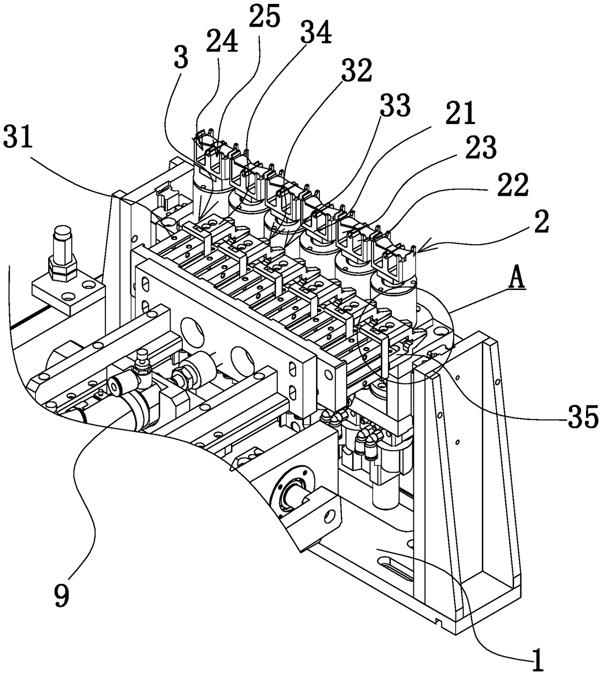
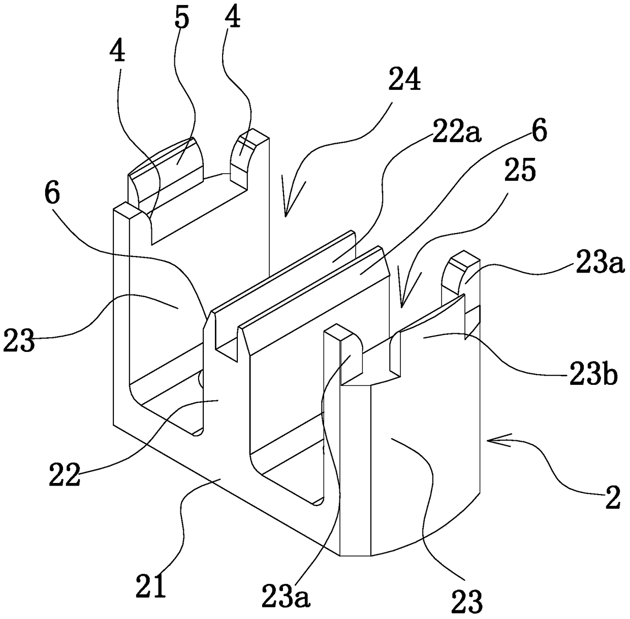
[0032] Such as Figure 1 to Figure 6 As shown, the double-leaf needle hub includes a tube-shaped needle handle 7 and two blades 8 connected to the outer wall of the needle handle 7 . The clamping structure of the double-leaf needle holder is set on the medical accessories assembly machine, such as figure 1 As shown, the assembly machine includes a frame 1, and the clamping structure includes a mechanical claw 3 arranged on the frame 1 and a positioning seat 2 capable of positioning a double-leaf needle seat. The positioning seat 2 is located on one side of the mechanical claw 3 .
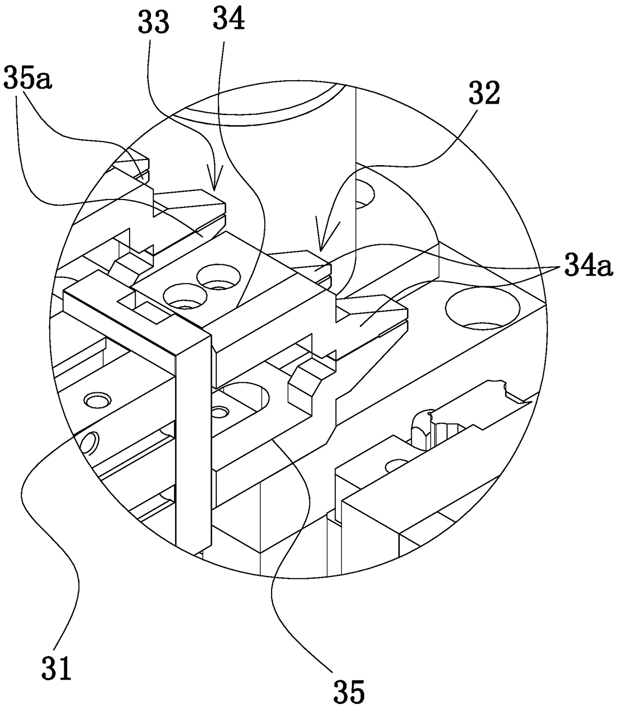
[0033] Mechanical claw 3 comprises driving source 31, left chuck 32 and right chuck 33 that are arranged at intervals on driving source 31, and driving source 31 can drive left chuck 32, right chuck 33 to clamp respectively or open, and left chuck The head 32 and the right chuck 33 can extend into the positioning seat 2 and clamp the double-leaf needle holder at the positioning seat 2 . Specifica...
Embodiment 2
[0038] The structure and principle of this embodiment are basically the same as that of Embodiment 1, the difference is that: Figure 7 As shown, the positioning structure includes a groove 23c on the overlapping surface of the side vertical plate 23. The side of the groove 23c facing the neutral plate 22 is open. tank wall. When the double-leaf needle holder is placed on the positioning seat 2, the edges of the blades 8 of the double-leaf needle holder can respectively overlap the groove bottom of the groove 23c, and the groove walls of the groove 23c can align the front and rear positions, left and right positions of the needle holder. The position is precisely positioned, so that the manipulator can grip the precise position of the double-leaf needle holder, and ensure that the manipulator can smoothly place the double-leaf needle holder into the positioning groove of the assembly fixture 10 .
Embodiment 3
[0040] The structure and principle of this embodiment are basically the same as that of Embodiment 1 or Embodiment 1. The difference is that the drive source 31 can also be two cylinders 9, wherein the upper clamp 34 is connected to one of the cylinders 9, and the lower clamp The sheet 35 is connected to another cylinder 9, and the piston rods of the two cylinders 9 are opposite. When the piston rods of the two cylinders 9 stretch out at the same time, it can drive the upper clip 34 and the lower clip 35 to move closer to each other, so that the left chuck 32 and right chuck 33 clamp respectively, otherwise then open respectively.
PUM
 Abstract
Description
Claims
Application Information
 - R&D Engineer
- R&D Manager
- IP Professional
- Industry Leading Data Capabilities
- Powerful AI technology
- Patent DNA Extraction
Browse by: Latest US Patents, China's latest patents, Technical Efficacy Thesaurus, Application Domain, Technology Topic.
© 2024 PatSnap. All rights reserved.Legal|Privacy policy|Modern Slavery Act Transparency Statement|Sitemap