
A device and method for quickly detecting the position of the lower step pad of a rolling mill

A detection device and a technology for step pads, which are applied in the field of step pads under rolling mills, can solve the problems that the finishing mill does not have the rolling conditions, the production interruption of the rolling line, and the long time, so as to shorten the processing time, improve the operation rate of the rolling mill, and improve the production cost. low effect

Active Publication Date: 2018-03-16
武汉钢铁有限公司
View PDF6 Cites 0 Cited by
  • Summary
  • Abstract
  • Description
  • Claims
  • Application Information

AI Technical Summary

Problems solved by technology

Once the position sensor of the lower step pad fails, the actual position of the step pad cannot be fed back to determine the height of the rolling line, and the finishing mill does not have the conditions for rolling steel
However, it takes a long time to replace the position sensor. Since the oil cylinder is filled with 210bar high-pressure hydraulic oil during production, the production must be interrupted and the valve should be closed to release pressure before replacing the position sensor of the lower step pad to ensure personal safety. The equipment is safe, and the whole process of replacing the sensor takes at least 45 minutes to complete
This will inevitably lead to the interruption of the continuous casting machine in the previous process and the interruption of the production of the rolling line

Method used


Image

  • A device and method for quickly detecting the position of the lower step pad of a rolling mill
  • A device and method for quickly detecting the position of the lower step pad of a rolling mill

Examples


Embodiment Construction

[0016] In order to better understand the present invention, the present invention will be further described below in conjunction with the accompanying drawings and embodiments.

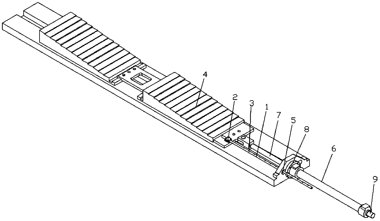
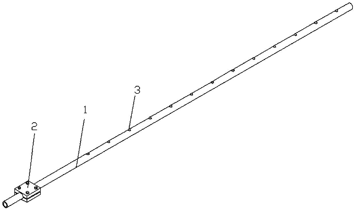
[0017] Such as Figure 1-2 As shown, a rapid detection device for the position of the lower step pad of a rolling mill includes a scale rod 1 and a fixed pipe clamp 2. Same number of stages as lower step pad 4.

[0018] The reading part can be a bump or a groove or a straight line, etc. The number of the reading part is thirteen, which corresponds to the number of steps of the lower step pad, and the distance between two adjacent reading parts is 150mm .

[0019] The scale rod is a cylindrical rod, and the fixed pipe clamp consists of two symmetrically arranged rectangular blocks with a semicircular groove in the center. The two sides of the two rectangular blocks are connected by bolts, and the diameter of the semicircular groove is slightly smaller than the scale. The diameter of the rod.

[002...


PUM


Abstract

The invention provides a fast detection device and method for the position of a lower step liner of a rolling mill. The device comprises a ruler rod and a fixing pipe clamp, wherein the front end of the ruler rod is connected with the fixing pipe clamp, and a plurality of stage reading parts are uniformly arranged on the ruler rod at intervals; the number of the stage reading parts corresponds to the number of stages of the lower step liner, and the number of stages of the lower step liner is determined by observing the number of the stage reading parts. The fast detection device is low in manufacture cost, is suitable for the bad environment of sites, and is easily maintained and used. The method is easily popularized.

Description

technical field [0001] The invention belongs to the technical field of a step pad under a rolling mill in a hot rolling mill, and in particular relates to a device and method for quickly detecting the position of a step pad under a rolling mill. Background technique [0002] The premise of hot-rolled strip rolling is to ensure that the rolling horizontal lines of each stand must be at the same level, but with the use of rolls (working rolls and backup rolls), it will inevitably lead to loss and replacement of rolls, which requires The height difference of the rolling line is compensated by adjusting the position of the lower step pad to ensure that the rolling level remains unchanged. [0003] The existing method for determining the position of the lower step pad of the rolling mill is to calculate the feedback value of the position sensor built in the telescopic oil cylinder of the lower step pad. Once the position sensor of the lower step pad fails, the actual position of...

Claims


Application Information

Patent Timeline
Patent Type & Authority Patents(China)
IPC IPC(8): B21B38/00
CPCB21B38/00
Inventor 刘超仇丹圣叶盛杨洲董江陶桂林马醇三
Owner 武汉钢铁有限公司
Learn More