
Manual stamping device

A punching device and punching die technology, which is applied in the field of aluminum alloy door and window processing equipment, can solve the problems of aluminum door and window profiles that are not easily washed off, multiple times of material handling, and low work efficiency, so as to reduce the labor intensity of workers, improve work efficiency, and punch holes. high pressure effect

Inactive Publication Date: 2016-01-20
湖南盛世美景门窗工程有限公司
View PDF8 Cites 1 Cited by
  • Summary
  • Abstract
  • Description
  • Claims
  • Application Information

AI Technical Summary

Problems solved by technology

The tools used are often hand electric drills, hand saws, etc. The disadvantages are low work efficiency, high labor intensity, and low product precision.
[0005] Among them, the power of the pneumatic punching machine is insufficient, the aluminum door and window profiles are not easy to wash off, the efficiency is low, and the failure rate is high; the structure of the general punching machine is heavy and complicated, which is not conducive to working on a moving construction site, low efficiency, high cost, and high energy consumption during operation.
Some stamping dies have low integration and need to move materials multiple times during use, resulting in low efficiency

Method used


Image

  • Manual stamping device
  • Manual stamping device
  • Manual stamping device

Examples


Embodiment Construction

[0015] The specific embodiments of the present invention will be described in further detail below with reference to the accompanying drawings.

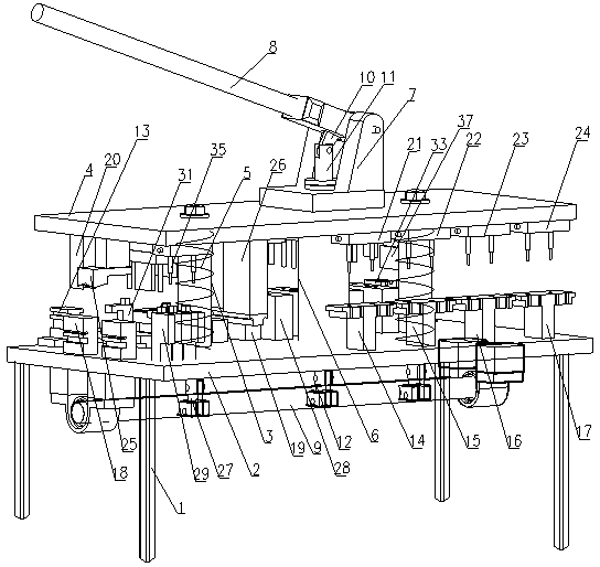
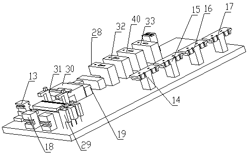
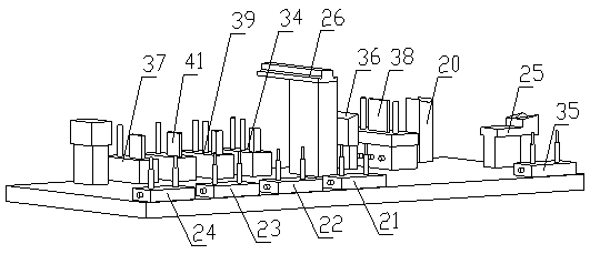
[0016] like Figure 1 to Figure 3 The shown manual punching device for processing aluminum alloy door and window components includes a frame 1, a lower template 2 is connected to the top of the frame 1, an upper template 4 is slidably connected to the lower template 2 through two sliding rods 3, and two return springs 5. It is located between the lower template 2 and the upper template 4, and is respectively sleeved on the outside of the two sliding bars 3. The sliding sleeve 6 is connected to the lower template 2 and is slidably connected with the upper template 4 and extends above the upper template 4. The hinge seat 7 is connected to the upper template 4. The top end of the sliding sleeve 6 is connected, one end of the lever 8 is hinged with the hinge seat 7 through the hinge shaft, the eccentric shaft 9 is rotatably connected und...


PUM


Abstract

The invention relates to a manual stamping device which is used for stamping and milling of aluminum alloy door and window components. The manual stamping device comprises a rack, a lower mold plate, an upper mold plate, a sliding rod, a reset spring, a sliding sleeve, a hinge base, a lever, an eccentric shaft, a first connecting rod, a second connecting rod, a third connecting rod, a fourth connecting rod, a sliding wheel notch mold stamping base, a fan blade upper portion inner-side mold stamping base, a fan blade upper portion outer-side mold stamping base, a fan blade lower portion inner-side mold stamping base, a fan blade lower portion outer-side mold stamping base, a water flushing and draining hole mold base, a trimming mold base, an angle code hole opening mold base, a rib stamping mold base, a fan blade edge cutting mold base, a vertical hinged door lock hole opening mold base, a vertical hinged door pressing line cutting opening mold base, a fan blade hole opening mold, a sliding wheel notch stamping mold, a fan blade upper portion inner-side stamping mold, a fan blade upper portion outer-side stamping mold, a fan blade lower portion inner-side stamping mold, a fan blade lower portion outer-side stamping mold, a water flushing and draining hole mold, a trimming mold, an angle code hole opening mold, a rib stamping mold, a fan blade edge cutting stamping mold, a vertical hinged door lock hole opening mold, a vertical hinged door pressing line cutting opening mold and a fan blade hole opening stamping mold. The sliding wheel notch mold stamping base, the fan blade upper portion inner-side mold stamping base, the fan blade upper portion outer-side mold stamping base, the fan blade lower portion inner-side mold stamping base, the fan blade lower portion outer-side mold stamping base, the water flushing and draining hole mold base, the trimming mold base, the angle code hole opening mold base, the rib stamping mold base, the fan blade edge cutting mold base, the vertical hinged door lock hole opening mold base, the vertical hinged door pressing line cutting opening mold base and the fan blade hole opening mold are connected to the lower mold plate; and the sliding wheel notch stamping mold, the fan blade upper portion inner-side stamping mold, the fan blade upper portion outer-side stamping mold, the fan blade lower portion inner-side stamping mold, the fan blade lower portion outer-side stamping mold, the water flushing and draining hole mold, the trimming mold, the angle code hole opening mold, the rib stamping mold, the fan blade edge cutting stamping mold, the vertical hinged door lock hole opening mold, the vertical hinged door pressing line cutting opening mold and the fan blade hole opening stamping mold are connected to the upper mold plate.

Description

technical field [0001] The invention relates to the technical field of aluminum alloy door and window processing equipment, in particular to a manual punching device for punching aluminum alloy door and window components. Background technique [0002] Aluminum alloy windows have beautiful appearance, sealing and high strength, and are widely used in the field of construction engineering. In the field of construction, aluminum alloy doors and windows are commonly used to encapsulate balconies. In the process of aluminum profile doors and windows, it is necessary to stamp and process the profiles for making aluminum doors and windows, and the aluminum alloy door and window profiles are cut, riveted or pinned. The profiles are processed into holes, openings, grooves, etc. for connection. The tools used are often hand electric drills, hand saws, etc. The disadvantages are low work efficiency, high labor intensity and low product accuracy. The existing aluminum alloy doors and...

Claims


Application Information

Patent Timeline
Patent Type & Authority Applications(China)
IPC IPC(8): B21D35/00B21D37/10B21D28/34B21D28/14
Inventor 唐军李良元
Owner 湖南盛世美景门窗工程有限公司
Learn More