Machining device suitable for cutting round stainless steel sheet

A stainless steel sheet and processing device technology, applied in auxiliary devices, metal processing, metal processing equipment, etc., can solve the problems of stainless steel plate material waste, manual movement of plates, etc., and achieve the effect of improving utilization rate, mechanization of operation, and improvement of qualified rate

Inactive Publication Date: 2016-01-20
CHENGDU XINDU SANLI PLASTIC CO LTD
View PDF5 Cites 2 Cited by
  • Summary
  • Abstract
  • Description
  • Claims
  • Application Information

AI Technical Summary

Problems solved by technology

[0009] The purpose of the present invention is to solve the problem that the existing plasma cutting machine needs to manually move the plate when cutting the stainless steel plate, resulting in the waste of a large amount of stainless steel plate material, and to provide a processing method suitable for cutting round stainless steel plate that is easy to operate and saves raw materials device

Method used


Image

  • Machining device suitable for cutting round stainless steel sheet
  • Machining device suitable for cutting round stainless steel sheet
  • Machining device suitable for cutting round stainless steel sheet

Examples


Embodiment 1

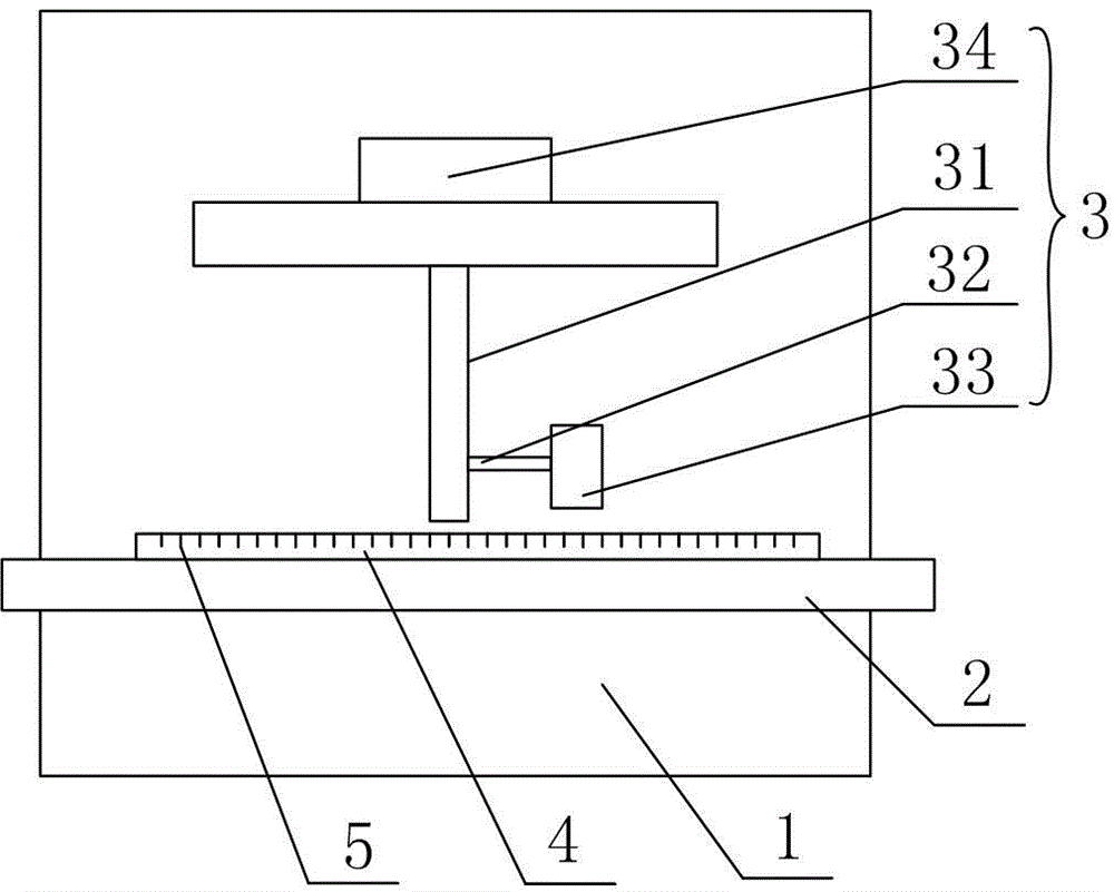
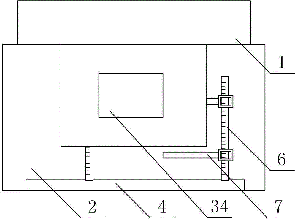
[0032] Processing equipment suitable for cutting round stainless steel sheets, such as figure 1 , figure 2 and image 3 As shown, it includes a cutting machine mounting frame 1, a plate fixing platform 2 and a plasma cutting mechanism 3 arranged on the cutting machine mounting frame 1;

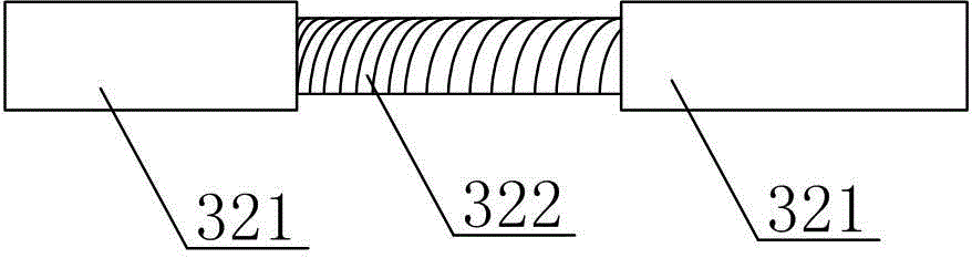
[0033] Described plasma cutting mechanism 3 comprises the rotary bar 31 that top is connected on the cutting machine installation frame 1, the plasma cutting head 33 that is fixed on the bottom end of rotary bar 31 by transverse extension bar 32, and the drive motor 34 that drives rotary bar 31 to rotate; The transverse extension rod 32 includes an inner rod 321 provided with an external thread, and two outer rods 322 provided with an outer rod 322; one end of one of the outer rods 322 is threadedly connected with the inner rod 321, and the other end is connected with the bottom end of the rotating rod 31 For fixed connection, one end of the other outer rod 322 is threadedly connected with ...

Embodiment 2

[0035] The difference between this embodiment and Embodiment 1 is that in this embodiment, the structure of the limit block 4 and the scale 5 is added, and the specific setting method is as follows:

[0036] The plate fixing platform 2 is provided with a limit block 4; the limit block 4 is provided with a scale 5.

Embodiment 3

[0038] The difference between this embodiment and embodiment 2 is: the structure of pointer 6 and marking rod 7 is added in this embodiment, and the specific setting method is as follows:

[0039] The limiting block 4 is also provided with a chute, and two pointers 6 parallel to each other are installed in the chute, and the pointers 6 are located in a plane parallel to the plate fixing platform 2 and perpendicular to the chute. The pointer 6 is also provided with a scale, and a marking rod 7 perpendicular to the pointer 6 is sleeved thereon.


PUM


Abstract

The invention discloses a machining device suitable for cutting a round stainless steel sheet. The machining device comprises a cutting machine installing rack, a sheet fixing platform and a plasma cutting mechanism, wherein the sheet fixing platform and the plasma cutting mechanism are arranged on the cutting machine installing rack. The machining device is characterized in that the plasma cutting mechanism comprises a rotary rod with the top end connected to the cutting machine installing rack, and a plasma cutting head fixed to the bottom end of the rotary rod through a transversely-stretching rod; the transversely-stretching rod comprises an inner rod with an external thread and two outer rods; and one end of one outer rod is in threaded connection with the inner rod, the other end of one outer rod is fixedly connected with the bottom end of the rotary rod, one end of the other outer rod is in threaded connection with the inner rod, and the other end of the other outer rod is fixedly connected with the plasma cutting head. The machining device has the beneficial effects that operation is easy and convenient, and raw materials are saved.

Description

technical field [0001] The invention relates to a cutting device, in particular to a processing device suitable for cutting circular stainless steel sheets. Background technique [0002] With the development of the modern mechanical processing industry, the requirements for cutting quality and precision are constantly improving, and the requirements for improving production efficiency, reducing production costs, and highly intelligent automatic cutting functions are also increasing. The development of CNC cutting machines must adapt to the requirements of the development of modern machining industry. Cutting machine is divided into flame cutting machine, plasma cutting machine, laser cutting machine, water cutting and so on. The laser cutting machine has the fastest efficiency, the highest cutting precision, and the cutting thickness is generally small. The cutting speed of the plasma cutting machine is also very fast, and the cutting surface has a certain slope. The flam...

Claims


Application Information

Patent Timeline
Patent Type & Authority Applications(China)
IPC IPC(8): B23K10/00B23K37/02B23K101/18B23K103/04
CPCB23K10/00B23K37/027B23K2101/18B23K2103/04
Inventor 刘润全
Owner CHENGDU XINDU SANLI PLASTIC CO LTD
Why Eureka
Try Eureka