Device for grabbing steel in pneumatic manner

A technology of steel materials and generating devices, applied in cranes and other directions, can solve the problem of low degree of integration

Inactive Publication Date: 2016-01-20
WUXI QINGYANG MACHINERY MFG
View PDF7 Cites 6 Cited by
  • Summary
  • Abstract
  • Description
  • Claims
  • Application Information

AI Technical Summary

Problems solved by technology

Less integr...

Method used


Image

  • Device for grabbing steel in pneumatic manner

Examples


Embodiment 1

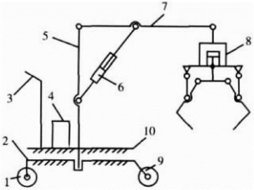
[0018] as attached figure 1 As shown, the rear end of the base 2 is connected with two rollers 1, which can roll on the ground, but cannot turn. The base 2 is connected with a turntable 10, and the turntable 10 is connected with the base 2 through a rotating motor, and the turntable 10 can rotate in a circle, so that the movement of the device is more flexible and convenient. A hold-up bar 3 is fixed on the turntable 10, and is used for the worker's handrail to operate the device. An air pressure generating device 4 is installed at the front end of the hold-up bar 3, and the air pressure generating device 4 supplies air to the air cylinder to control the telescopic length of the air cylinder. The bracket 5 is fixed at the center of the base 2, the swing rod 7 is connected to the bracket 5 through a hinge, and the two can rotate relative to each other. Hinge connection, telescopic pneumatic cylinder 6 can utilize its telescopic length to control the movement of swing rod 7 in ...


PUM


Abstract

The invention provides a device for grabbing steel in a pneumatic manner. The rear end of a base is connected with two wheels which can roll on the ground but can not turn. The front end of the base is connected with steering wheels, wherein direction rotation of a trolley can be achieved through the steering wheels. A rotating table is connected to the base and connected with the base through a rotating motor, the rotating table can circumferentially rotate, and therefore the device can more flexibly, easily and conveniently move. A holding rod is fixed to the rotating table so that a worker can hold the holding rod to operate the device. A gas pressure generation device is arranged at the front end of the holding rod and supplies gas to a pneumatic cylinder so that the telescopic length of the pneumatic cylinder can be controlled. A support is fixed to the central position of the base. A swing rod is connected with the support through a hinge. The swing rod and the support can rotate and move relatively. Meanwhile, the tail of the telescopic pneumatic cylinder is connected with the support through a hinge, a top rod and the swing rod are connected through a hinge, and therefore movement, in the vertical plane, of the swing rod can be controlled by the telescopic pneumatic cylinder through the telescopic length of the telescopic pneumatic cylinder, and gripper jaws pick up steel through stretching and clamping.

Description

technical field [0001] The invention relates to the fields of machinery manufacturing and steel production, in particular to a device for grabbing steel by pneumatic power. Background technique [0002] Mechanical automation mainly refers to the application of automation technology in the machinery manufacturing industry to realize the continuous automatic production of processing objects, realize the optimized and effective automatic production process, and accelerate the processing transformation and flow speed of production inputs. The application and development of mechanical automation technology is the main means of technological transformation and technological progress of the machinery manufacturing industry and the main direction of technological development. The technical level of mechanical automation not only affects the development of the entire machinery manufacturing industry, but also has a great direct impact on the technological progress of various sectors ...

Claims


Application Information

Patent Timeline
IPC IPC(8): B66C23/06
Inventor 唐靖岚
Owner WUXI QINGYANG MACHINERY MFG
Why Eureka
Try Eureka