Low inertia spring torsion bar constant force mechanism

A torsion bar type, torsion bar technology, applied in the spring mechanism, hoisting device, etc., to achieve the effect of a wide range of applicable torque values, low moment of inertia, and small impact interference

Active Publication Date: 2017-06-20
HARBIN INST OF TECH
View PDF6 Cites 0 Cited by
  • Summary
  • Abstract
  • Description
  • Claims
  • Application Information

AI Technical Summary

Problems solved by technology

[0007] The present invention is to solve the limitation problem of the existing passive constant force output device, and now provides a low inertia spring torsion bar type constant force mechanism

Method used


Image

  • Low inertia spring torsion bar constant force mechanism
  • Low inertia spring torsion bar constant force mechanism

Examples


specific Embodiment approach 1

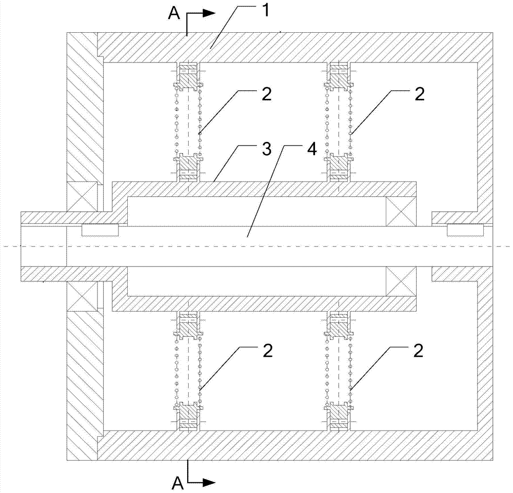
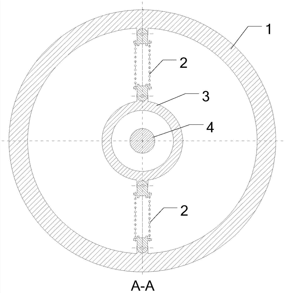
[0021] Specific implementation mode one: refer to figure 1 with figure 2 Specifically explain this embodiment, the low inertia spring torsion bar type constant force mechanism described in this embodiment, it includes: constant force mechanism body, this constant force mechanism body includes: constant force mechanism input shaft 3 and constant force mechanism output reel 1. The head end of the output reel 1 of the constant force mechanism is provided with an opening, the input shaft 3 of the constant force mechanism is located inside the output reel 1 of the constant force mechanism, and the head end of the input shaft 3 of the constant force mechanism is output from the reel 1 of the constant force mechanism The first end goes out and is connected with the inner wall of the opening through the bearing,

[0022] It also includes: n springs 2 and torsion bars 4, where n is a positive integer;

[0023] n springs 2 are evenly distributed between the output reel 1 of the const...

specific Embodiment approach 2

[0030] Embodiment 2: This embodiment further explains the low-inertia spring torsion bar type constant force mechanism described in Embodiment 1. In this embodiment, the n springs 2 are all cylindrical helical compression springs.

specific Embodiment approach 3

[0031] Specific embodiment three: This embodiment is to further explain the low inertia spring torsion bar type constant force mechanism described in specific embodiment one. In this embodiment, the two ends of n springs 2 are respectively connected to the constant force mechanism The input shaft 3 is hinged to the output reel 1 of the constant force mechanism.


PUM


Abstract

A low inertia spring torsion bar type constant force mechanism belongs to a constant force loading mechanism. The invention aims to solve the limitation problem of the existing passive constant force output device. In the low-inertia spring torsion bar type constant force mechanism of the present invention, the two ends of a plurality of springs are respectively hinged with the input shaft of the constant force mechanism and the output reel of the constant force mechanism; the torsion bar is located inside the input shaft of the constant force mechanism, and the torsion bar The two ends of the constant force mechanism are respectively fixedly connected with the input shaft of the constant force mechanism and the output reel of the constant force mechanism. This structure fully considers the use requirements of the constant force mechanism. Achieve continuous output of constant torque throughout the transmission process. The invention has the outstanding advantages of simple structure, low inertia, high torque and high sensitivity, and strong versatility. It provides constant force output for high-frequency changing loads, and has a wide range of applicable torque values, high stability of output torque values, and low moment of inertia. Low inertia spring torsion bar constant force mechanism.

Description

technical field [0001] The invention belongs to a constant force loading mechanism, in particular to a low inertia spring torsion bar type constant force mechanism. Background technique [0002] Constant force loading mechanism is widely used in paper roll, thermal power generation, material testing, aerospace equipment and other fields, and it can directly affect the safety and reliability of equipment. Especially in the field of aerospace, it is often used as a ground verification method to verify the performance of spacecraft through the constant force mechanism to provide micro-low gravity compensation. The traditional gravity compensation methods include counterweight balance, air flotation, water flotation, suspension method, etc. Among them, the gravity simulation of the suspension method has two methods: active compensation and passive compensation. [0003] After searching the literature of the prior art, it is found that the passive constant force output devices c...

Claims


Application Information

Patent Timeline
Patent Type & Authority Patents(China)
IPC IPC(8): B66D1/30
Inventor 刘振高海波牛福亮邓宗全李楠丁亮
Owner HARBIN INST OF TECH
Why Eureka
Try Eureka