Oil recovery method combining steam flooding and fire flooding

A steam flooding and fire flooding technology, which is applied in the direction of production fluid, earthwork drilling, wellbore/well components, etc., can solve the problems of reduced oil production rate, difficulty in producing reserves above the interlayer, and unavailability of the interlayer

Active Publication Date: 2016-01-20
PETROCHINA CO LTD
View PDF10 Cites 6 Cited by
  • Summary
  • Abstract
  • Description
  • Claims
  • Application Information

AI Technical Summary

Problems solved by technology

However, in the process of SAGD production, due to the development of interlayers in the development area, which prevents the overlying of the steam chamber and affects the expansion of the steam chamber, the continuous steam injection of the steam injection well will cause the pressure of the steam chamber to rise rapidly, and the steam does not undergo sufficient heat exchange with the formation crude oil. It is produced by the horizontal production well under the action of the pressure difference, the thermal efficiency is low, a large amount of steam flows into the horizontal well, and the steam channeling of the horizontal well is relatively serious, which greatly affects the SAGD development effect, making it difficult to develop the reserves above the interlayer
At present, the method of reducing the steam injection intensity and ensuring a reasonable steam cavity pressure is adopted in this situation in China. Although it can suppress steam channeling and improve thermal efficiency, it still cannot use the remaining oil above the interlayer, and also reduces the oil recovery rate, which is not good. Give full play to the advantages of SAGD's high oil recovery rate and high recovery factor
[0004] However, if steam flooding is implemented, steam flooding is suitable for ordinary heavy oil (crude oil viscosity < 10000mmPa.s), and the viscosity of super heavy oil crude oil is too high (it will reach tens of thousands of mmPa.s or even hundreds of thousands of mmPa.s). Poor, severe gas channeling, poor economic benefits, beyond the requirements of steam flooding
[0005] For this technical problem, no effective solution has been proposed

Method used


Image

  • Oil recovery method combining steam flooding and fire flooding
  • Oil recovery method combining steam flooding and fire flooding
  • Oil recovery method combining steam flooding and fire flooding

Examples


Embodiment Construction

[0043]The details of the present invention can be understood more clearly with reference to the accompanying drawings and the description of specific embodiments of the present invention. However, the specific embodiments of the present invention described here are only for the purpose of explaining the present invention, and should not be construed as limiting the present invention in any way. Under the teaching of the present invention, the skilled person can conceive any possible modification based on the present invention, and these should be regarded as belonging to the scope of the present invention.

[0044] It should be noted that the directional words in the present invention, such as "terminal" and "down", can be understood as being away from the direction of the wellhead, and "upper" can be understood as facing the direction of the wellhead. As used, the term "and / or" includes any and all combinations of one or more of the associated listed items. In addition, the ...


PUM


Abstract

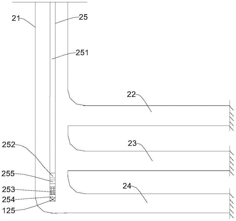
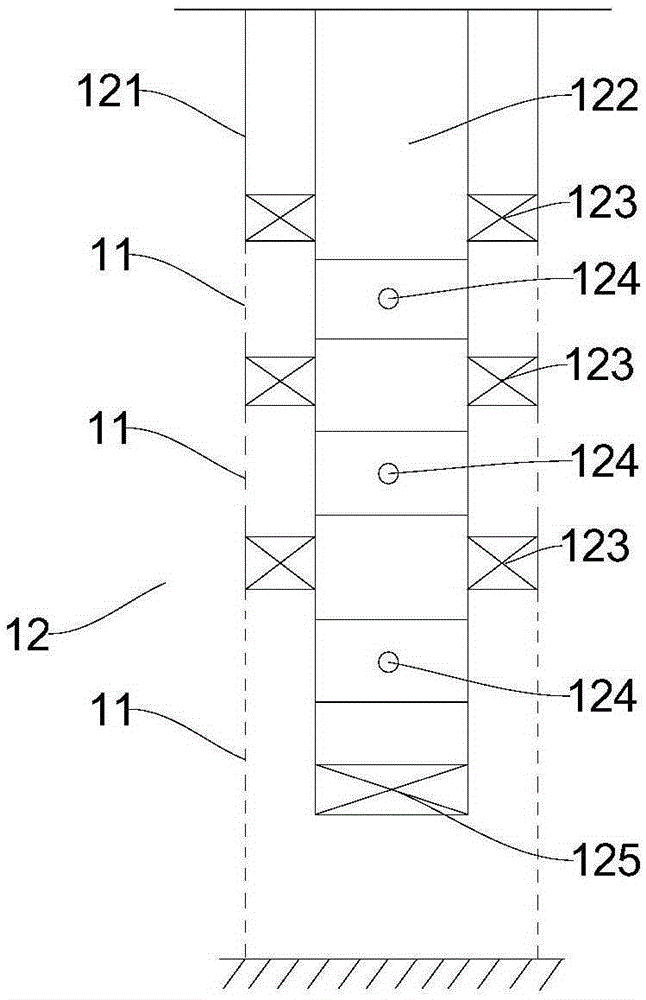
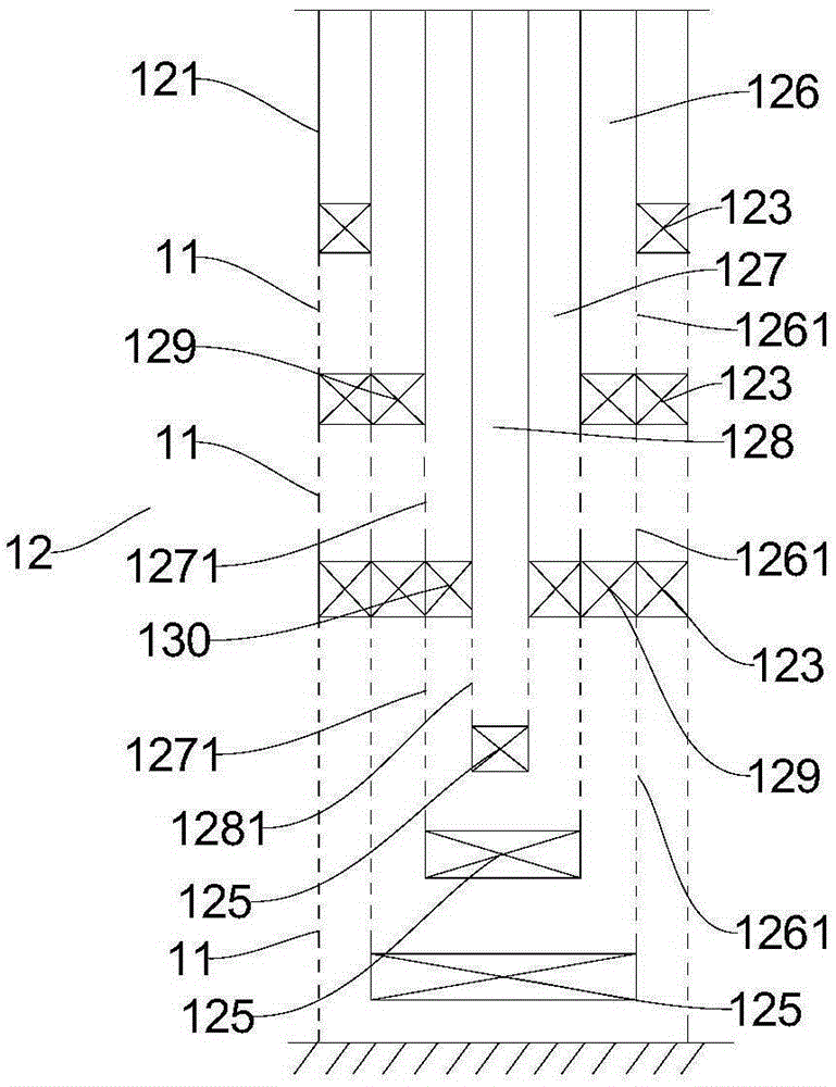
The invention provides an oil recovery method combining steam flooding and fire flooding. The method includes: arranging a vertical well and at least one horizontal well; injecting air into the vertical well to produce tail gas, and allowing the horizontal wells to discharge the tail gas; injecting high-temperature steam into a third oil layer through the vertical well, and stopping the high-temperature steam injection after the high-temperature steam is injected for first set time; performing ignition and gas injection on a second oil layer through the vertical well to allow the second oil layer to combust so as to form a fire line, and stopping air injection when the distance between the fire line and the tail ends of the horizontal wells reaches preset length; injecting high-temperature steam into a first oil layer and the third oil layer at the same time through the vertical well to produce flowing oil, allowing the horizontal wells to lift the flowing oil to the ground, and stopping the high-temperature steam injection when the high-temperature steam is injected for second preset time; injecting air into the first oil layer, the second oil layer and the third oil layer through the vertical well so as to perform oil layer reaction, and allowing the horizontal wells to lift the produced flowing oil to the ground. By the method, steam flooding oil recovery and fire flooding oil recovery can be performed in a layered manner after the air and / or high-temperature steam are injected in a layered manner through the vertical well.

Description

technical field [0001] The invention relates to the technical field of petroleum exploitation, in particular to a combined oil recovery method of steam flooding and fire flooding. Background technique [0002] For medium-thick ultra-heavy oil reservoirs, an interlayer is often formed in the formation. An interlayer is a non-permeable layer that prevents or controls fluid movement, and its thickness varies greatly, ranging from tens of centimeters to several meters thick, up to tens of meters thick. If conventional oil recovery methods are used to exploit ultra-heavy oil reservoirs with interlayers, because the interlayers are not connected to the heavy oil, heat transfer between the heavy oil and heat will be prevented to produce flowable oil, which will affect oil recovery efficiency. [0003] At present, SAGD is used to exploit ultra-heavy oil reservoirs with interlayers. However, in the process of SAGD production, due to the development of interlayers in the development...

Claims


Application Information

Patent Timeline
IPC IPC(8): E21B43/24E21B43/243E21B43/30
Inventor 于晓聪龙华阚长宾张思敏韩冰李小龙
Owner PETROCHINA CO LTD
Why Eureka
Try Eureka