Eureka AIR delivers breakthrough ideas for toughest innovation challenges, trusted by R&D personnel around the world.

A hydraulic pipeline fluid pulsation damping device based on piezoelectric shunt damping technology

A hydraulic pipeline and pulsation attenuation technology, which is applied to pipe components, pipes/pipe joints/fittings, mechanical equipment, etc., can solve problems such as high driving voltage or magnetic field strength, overheating of actuators, complex active control systems, etc., to achieve Improve the pulsation attenuation effect and maintain the effect of dynamic characteristics

Inactive Publication Date: 2017-10-24
SOUTHWEST JIAOTONG UNIV
View PDF6 Cites 0 Cited by
  • Summary
  • Abstract
  • Description
  • Claims
  • Application Information

AI Technical Summary

Problems solved by technology

With the development of the hydraulic system, the active control method of the hydraulic fluid pulsation studied by the predecessors has also exposed many shortcomings, which are summarized as follows: (1) When the servo actuator is installed, due to the need to produce equal amplitude and phase difference The secondary pulsation wave, which makes the actuator volume larger; and because in the high-pressure hydraulic system, the actuator has to bear a large load, so that its driving voltage or magnetic field strength is very large, which will cause the actuator to overheat (2) Because the high-pressure fluid in the pipeline will increase the rigidity of the pipeline, if the pipeline is to be deformed, a large execution force is required, and the deformation of the pipe wall of the hydraulic system is used to generate pressure pulsation waves. The active control of fluid pulsation is mostly used in low-pressure hydraulic pipeline systems, and it is not suitable for high-pressure hydraulic systems; (3) Although active filtering is effective in eliminating pulsation, the active control system is complex and expensive, so it is currently only in the laboratory Level

Method used


Image

  • A hydraulic pipeline fluid pulsation damping device based on piezoelectric shunt damping technology
  • A hydraulic pipeline fluid pulsation damping device based on piezoelectric shunt damping technology
  • A hydraulic pipeline fluid pulsation damping device based on piezoelectric shunt damping technology

Examples


Embodiment Construction

[0018] The present invention will be further described in detail with reference to the accompanying drawings and embodiments.

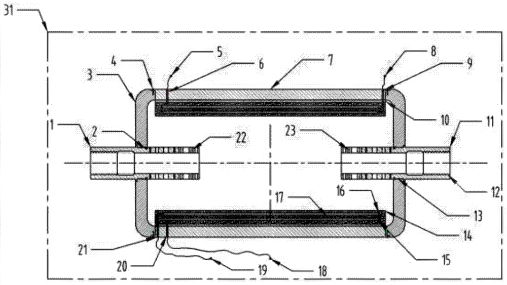
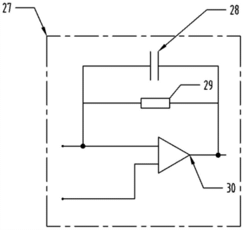
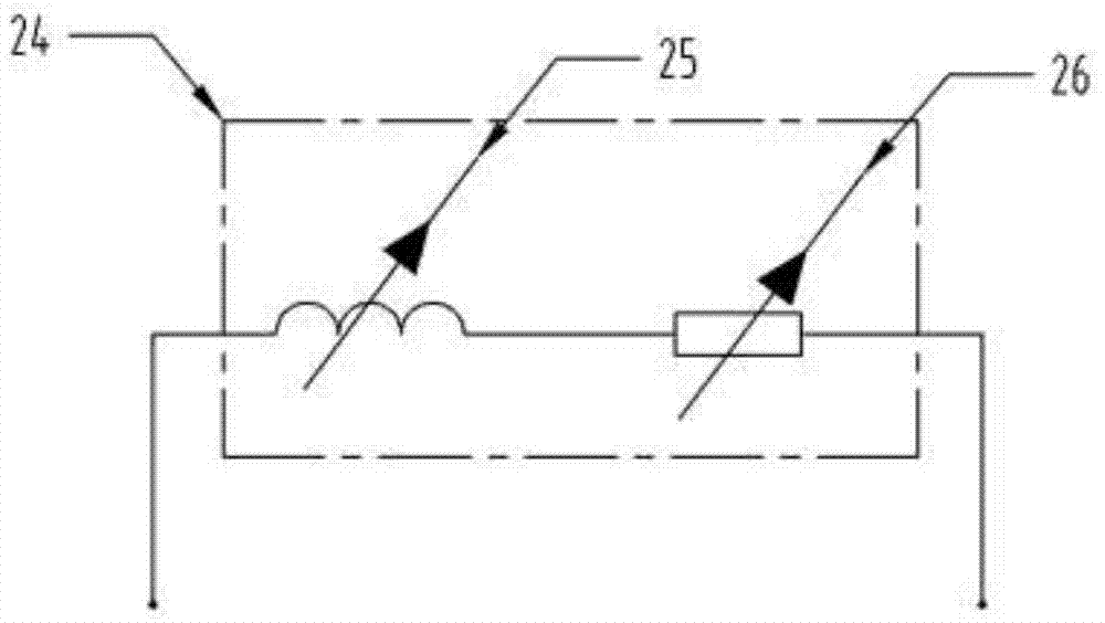
[0019] The present invention is based on the hydraulic pipeline fluid pulsation attenuation device based on piezoelectric shunt damping technology, such as figure 1 , 2 , 3, the inlet pipe 1 and the outlet pipe 11 extend into the cavity of the attenuator, and are connected to the end cover 3 through the threaded part 13 . The left and right end caps 3 of the attenuator and the upper and lower end caps 7 are connected by slotted cylindrical head screws 4; in order to increase the output voltage of the charge amplifier circuit 27, the PVDF piezoelectric film 17 is connected in parallel, and on both sides of the PVDF piezoelectric film Bonding aluminum electrodes (15 and 16) to make a PVDF piezoelectric film sensor; wrapping the PVDF piezoelectric film 17 and the aluminum electrodes with epoxy resin 14, and then bonding them on by 502 adhesive 10, On t...


PUM


Abstract

The invention discloses a hydraulic pipeline fluid pulsation attenuation device based on piezoelectric shunt damping technology. The middle part of the attenuator (31) is a cuboid sealed cavity, and the left and right ends of the cavity are respectively provided with inlet circular pipes for hydraulic fluid flow. (1) and the outlet pipe (11) that flows out of the hydraulic fluid, the inlet pipe (1) and the outlet pipe (11) extend into the cavity of the attenuator; the upper and lower parts of the inner surface of the cavity are respectively provided with PVDF piezoelectric Thin film, the PVDF piezoelectric film is provided with lead-out wires leading out of the sealed cavity from both sides to form an electrical connection with the outside. The invention utilizes active filtering to attenuate low-frequency pulsation, passive filtering to attenuate medium and high-frequency pulsation, and combines active and passive filtering, which can not only maintain the original dynamic characteristics of the hydraulic system, but also improve the pulsation attenuation effect in a wider frequency band.

Description

technical field [0001] The invention belongs to the field of hydraulic pipeline fluid pulsation control, in particular to a hydraulic pipeline fluid pulsation attenuation device based on piezoelectric shunt damping technology. Background technique [0002] Due to the structural characteristics of the axial piston pump itself and the huge pressure difference that causes the oil to recoil back into the oil cylinder, the plunger pump has both inherent flow pulsation and backflush flow pulsation, and the backflush flow pulsation is the main one. When the flow pulsation output by the pump flows through the hydraulic pipeline, pressure pulsation will be generated due to the existence of throttling ports, valve ports, etc. in the pipeline. The pressure and flow pulsation in the pipeline will induce pipeline vibration and generate noise, thereby reducing the life of hydraulic components and causing catastrophic accidents in severe cases. Therefore, it is of great practical signific...

Claims


Application Information

Patent Timeline
Patent Type & Authority Patents(China)
IPC IPC(8): F16L55/04F16L55/033
CPCF16L55/033F16L55/04
Inventor 邓斌杨帆柯坚王国志于兰英
Owner SOUTHWEST JIAOTONG UNIV
Why Eureka
Eureka Blog
Learn More