Crankshaft rotation tool and method for rotating crankshaft

A crankshaft and tool technology, which is applied in the field of crankshaft turning tools, can solve the problems of laborious, low-efficiency moving back and forth operations, etc., and achieve the effects of simple structure, reliable friction and occlusal, and stable connection

Active Publication Date: 2016-01-20
GUANGXI YUCHAI MASCH CO LTD
View PDF6 Cites 2 Cited by
  • Summary
  • Abstract
  • Description
  • Claims
  • Application Information

AI Technical Summary

Problems solved by technology

[0002] During the engine assembly process, it is necessary to detect the coaxiality of the flywheel housing seam circle relative to the crankshaft by rotating the crankshaft. Since there is no suitable tool, it is necessary to install the detection tool at the rear end of the engine in actual operation, and then walk to In the middle of the engine, turn the crankshaft by hand to turn the crankshaft, and then go back to the rear end of the engine for inspection. The whole operation can only be completed by walking repeatedly. It is laborious to turn the crankshaft by turning the crankshaft, and the operation efficiency of walking back and forth Therefore, there is an urgent need to design and manufacture safe, reliable, and versatile crankshaft turning tools to reduce labor intensity and improve assembly efficiency

Method used


Image

  • Crankshaft rotation tool and method for rotating crankshaft
  • Crankshaft rotation tool and method for rotating crankshaft
  • Crankshaft rotation tool and method for rotating crankshaft

Examples


Embodiment 1

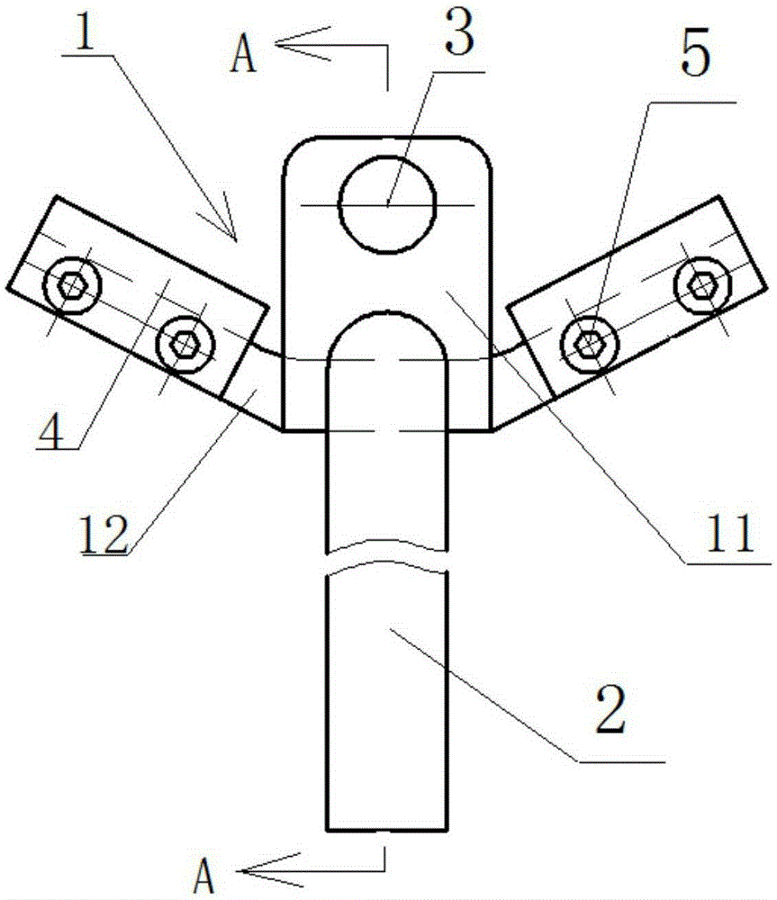
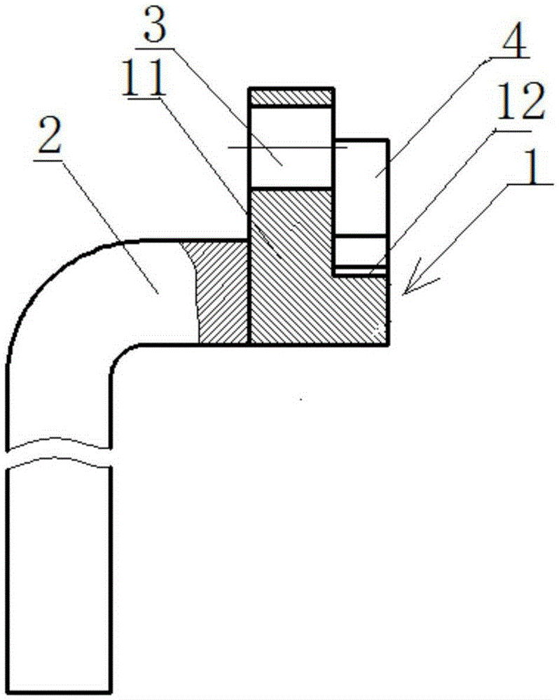
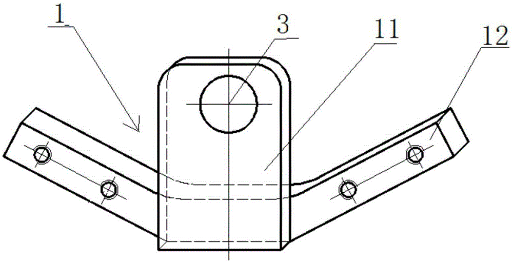
[0027] Such as Figure 1 to Figure 5 As shown, a crankshaft turning tool includes a positioning block 1 and a handle 2 connected to the positioning block 1. The positioning block 1 includes a main positioning block 11 and two auxiliary positioning blocks 12 arranged on both sides of the main positioning block 11, The auxiliary positioning block 12 is provided with an elastic member 4 for closely contacting the outer circle of the big end of the crankshaft, and the main positioning block 11 is provided with a positioning hole 3 for matching with a positioning pin on the end surface of the large end of the crankshaft.

[0028] Specifically, the angle α formed by the two auxiliary positioning blocks 12 is 125°. In this embodiment, the two auxiliary positioning blocks 12 are elongated, and the two auxiliary positioning blocks 12 protrude outward from both sides of the main positioning block 11 and face the positioning hole. 3. One side is obliquely arranged, and the two auxiliary...


PUM


Abstract

The present invention discloses a crankshaft rotation tool, comprising a locating block and a handle connected with the locating block, wherein the locating block comprises a main locating block and two auxiliary locating blocks arranged at two sides of the main locating block, each auxiliary locating block is provided with an elastic component used for being tightly contacted with an excircle of a big end of a crankshaft, and the main locating block is provided with a locating hole used for cooperating with a locating pin at the end face of the big end of the crankshaft. The present invention aims to provide the crankshaft rotation tool which is simple in structure, convenient and reliable in use, and capable of forwards and reversely rotating the crankshaft, at the same time, the present invention also provides a method for rotating the crankshaft by adopting the crankshaft rotation tool.

Description

technical field [0001] The invention relates to a tool for turning a crankshaft, in particular a crankshaft turning tool capable of forward and reverse rotation of a crankshaft. Meanwhile, the invention also provides a method for turning a crankshaft by using the crankshaft turning tool. Background technique [0002] During the engine assembly process, it is necessary to detect the coaxiality of the flywheel housing seam circle relative to the crankshaft by rotating the crankshaft. Since there is no suitable tool, it is necessary to install the detection tool at the rear end of the engine in actual operation, and then walk to In the middle of the engine, turn the crankshaft by hand to turn the crankshaft, and then go back to the rear end of the engine for inspection. The whole operation can only be completed by walking repeatedly. It is laborious to turn the crankshaft by turning the crankshaft, and the operation efficiency of walking back and forth Therefore, there is an ur...

Claims


Application Information

Patent Timeline
Patent Type & Authority Applications(China)
IPC IPC(8): G01B21/24F01B9/02
Inventor 罗广德
Owner GUANGXI YUCHAI MASCH CO LTD
Why Eureka
Try Eureka