
Superimposed wave attenuation probe used for core longitudinal and transverse wave measurement

A wave attenuation, longitudinal and transverse wave technology, applied to the measurement of ultrasonic/sonic/infrasonic waves, measuring devices, and the use of sound waves/ultrasonic/infrasonic waves to analyze solids, etc., can solve the problem of not being able to effectively absorb direct wave reflection, refraction waves, and core longitudinal and transverse waves. Accuracy can not be effectively guaranteed and other problems, to achieve reasonable structure, improve measurement accuracy, easy to use effect

Inactive Publication Date: 2016-01-20
CNPC XIBU DRILLING ENG
View PDF5 Cites 0 Cited by
  • Summary
  • Abstract
  • Description
  • Claims
  • Application Information

AI Technical Summary

Problems solved by technology

[0003] The present invention provides a superimposed wave attenuation probe for the measurement of rock core longitudinal and shear waves, which overcomes the above-mentioned deficiencies in the prior art, and can effectively solve the problem of rock core longitudinal and shear wave probes. It cannot effectively absorb its own direct wave, reflection, and refraction waves. The self-reflection and refraction waves of the core P-S wave probe will superimpose with the first wave to form a disordered wave, so that the measurement accuracy of the core P-S wave cannot be effectively guaranteed.

Method used


Image

  • Superimposed wave attenuation probe used for core longitudinal and transverse wave measurement

Examples


Embodiment Construction

[0016] The present invention is not limited by the following examples, and specific implementation methods can be determined according to the technical solutions of the present invention and actual conditions.

[0017] In the present invention, for the convenience of description, the description of the relative positional relationship of each component is based on the description attached to the description. figure 1 For example, the positional relationship of top, bottom, left, right, etc. is determined according to the layout direction of the drawings in the specification.

[0018] Below in conjunction with embodiment and accompanying drawing, the present invention will be further described:

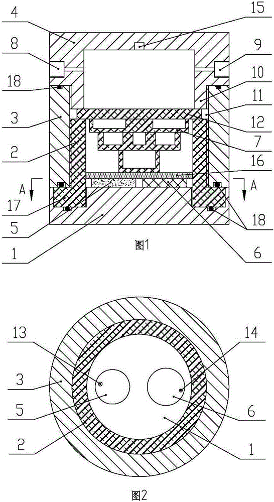
[0019] as attached figure 1 , 2 As shown, the superimposed wave attenuation probe for core longitudinal and shear wave measurement includes a longitudinal and transverse wave transmission plug 1, a probe attenuation sleeve 2, a tail connection sleeve 3, a probe cap 4, a shear wave ch...


PUM


Abstract

The invention relates to the technical field of core sound wave detection probes, and provides a superimposed wave attenuation probe used for core longitudinal and transverse wave measurement. The superimposed wave attenuation probe comprises a longitudinal and transverse wave transmission top, a probe attenuation sleeve, a tail connection sleeve, a probe sealing cap, a transverse wave wafer, a longitudinal wave wafer and a superimposed wave attenuator. The probe attenuation sleeve is fixedly arranged on the upper end face of the longitudinal and transverse wave transmission top. The probe attenuation sleeve and the lower end of the probe sealing cap are fixedly arranged together through the tail connection sleeve. The superimposed wave attenuation probe is reasonable and compact in structure and convenient to use; the upper portion of the transverse wave wafer and the upper portion of the longitudinal wave wafer are in a reverse tower shape, each layer of the superimposed wave attenuator is provided with a groove, and therefore direct waves, reflected waves and refracted waves are effectively absorbed and attenuated; the probe attenuation sleeve is arranged, and therefore direct waves from the longitudinal and transverse wave transmission top to the tail connection sleeve are effectively attenuated, the longitudinal and transverse wave transmission top can be free of superimposed wave interference when transmitting in and receiving head waves, and the measurement accuracy is improved.

Description

technical field [0001] The invention relates to the technical field of rock core acoustic wave measuring probes, and relates to a superimposed wave attenuation probe for measuring rock core longitudinal and transverse waves. Background technique [0002] For a long time, because the first wave of the probe measured by the core longitudinal and transverse waves is affected by the superposition of its own direct wave, reflected wave, and refracted wave, it is difficult to identify the interference of the first wave of the core direct wave being reflected, refracted and superimposed, and the measurement error of the core longitudinal and transverse waves is large. Especially for rock core shear wave measurement, because the shear wave lags behind the longitudinal wave, the head wave of the core shear wave direct wave is more affected by the superimposition of its own secondary longitudinal wave reflection and refraction waves. The reflection and refraction waves of the core lon...

Claims


Application Information

Patent Timeline
IPC IPC(8): G01N29/11G01H17/00
Inventor 蔡敏龙蔡晓颖
Owner CNPC XIBU DRILLING ENG
Learn More