Spiral pipe bending machine and pipe bending method

A pipe bender and spiral pipe technology, applied in the field of spiral pipe benders, can solve problems such as pipe jamming, insufficient position, complex structure, etc., and achieve the effects of reducing work intensity, ensuring complete removal, and adapting to a wide range

Active Publication Date: 2016-01-27
DONGGUAN ZHENGYANG ELECTRONICS MECHANICAL CO LTD
View PDF6 Cites 9 Cited by
  • Summary
  • Abstract
  • Description
  • Claims
  • Application Information

AI Technical Summary

Problems solved by technology

[0003] Traditional U-tube ( figure 1 ) can be completed by hand bending, while the equal-pitch spiral pipe (not shown) has a complicated structure, the labor intensity of hand bending is too large, and the product quality cannot be guaranteed, so a pipe bender is required for mechanical operation, as disclosed in Chinese Utility Model No. A kind of screw pipe bending machine, so that the pipe can be machined, reduce labor intensity, reduce cost and increase output
However, the pitch of the spiral pipe bent by this screw pipe bender is fixed. If the pitch needs to be widened or narrowed, the screw must be replaced.
And even if the screw rod is replaced, the following types of spiral tubes cannot be produced: the end of the spiral tube has a pre-bent head, and the pitch of the spiral part changes from wide to narrow, from narrow to wide, and the width and narrow intervals change. The reasons are as follows : (1) The pre-bending head needs to occupy a certain space, and the position of the traditional screw pipe bending machine is insufficient, resulting in the inability to locate; (2) The traditional screw pipe bending machine cannot determine the initial bending position of the pipe, which may easily cause the pipe to be stuck in the screw rod inside the screw groove, causing interference

Method used


Image

  • Spiral pipe bending machine and pipe bending method
  • Spiral pipe bending machine and pipe bending method
  • Spiral pipe bending machine and pipe bending method

Examples


Embodiment Construction

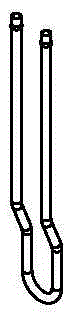
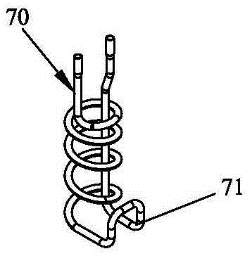
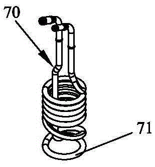
[0057] Please refer to Figure 4 and Figure 5 As shown, it shows the specific structure of the preferred embodiment of the present invention, which is a spiral pipe bender, which can bend spiral pipes with different pitches without replacing any parts (see figure 2 and image 3 ). The structure of the spiral pipe bender includes a frame 10 , a control system 20 installed in the frame 10 , a spindle rotation mechanism 30 , an auxiliary spindle concentric mechanism 40 , a screw feed mechanism 50 and a spiral tube pitch adjustment mechanism 60 .

[0058] Among them, such as Figure 5 As shown, the control system 20 includes a control host 21, a touch screen 22 installed on the table of the frame 10, the touch screen 22 is connected to the control host 21, and the control host 21 is electrically connected to the main shaft rotation mechanism 30, the auxiliary main shaft concentric mechanism 40, The driving part of the spiral tube pitch adjusting mechanism 60 and the screw fe...


PUM


Abstract

The invention discloses a spiral pipe bending machine and a pipe bending method. The spiral pipe bending machine structurally comprises a machine frame, and a control system, a main shaft rotating mechanism, an auxiliary main shaft concentration mechanism, a spiral pipe pitch regulating mechanism and a spiral feeding mechanism which are arranged in the machine frame. The spiral feeding mechanism and the spiral pipe pitch regulating mechanism are designed, and therefore a fixed manner of a traditional spiral rod is completely replaced, the pitch of a spiral pipe can be regulated to be freely changed in the pipe bending process, the bending work of spiral pipes of different types can be completed on a machine table, the whole operation process is easy and rapid to operate, operation difficulty can be greatly lowered for personnel, and the application range is wide.

Description

technical field [0001] The invention relates to the technology in the field of mechanical processing, in particular to a spiral pipe bending machine and a pipe bending method capable of automatically bending pipes such as urea pipes, water pipes, oil pipes, electric heating rods and the like. Background technique [0002] Traditional elbow types generally have U-shaped tubes ( figure 1 ) and equal-pitch spiral pipes (not shown), the more common ones are urea pipes, water pipes, oil pipes, electric heating rods, etc. These U-shaped pipes and equal-pitch spiral pipes are widely used in automobiles, electric heaters and other industries middle. For example, in the automotive industry, U-shaped tubes and equal-pitch spiral tubes are used for urea sensors. The urea sensor is installed in the urea tank. The urea tank stores the urea solution. The sensor is responsible for pumping out the liquid urea for use. When the urea solution is at minus 7 degrees It freezes easily and cann...

Claims


Application Information

Patent Timeline
Patent Type & Authority Applications(China)
IPC IPC(8): B21D11/06B21D11/22
Inventor 顾耿豪
Owner DONGGUAN ZHENGYANG ELECTRONICS MECHANICAL CO LTD
Why Eureka
Try Eureka