Building circular arc component perforating machine

An arc-shaped, architectural technology, used in portable drilling rigs, drilling/drilling equipment, workbenches, etc., can solve problems such as inaccurate position deviation, and achieve the effects of accurate positioning, compact device, and easy portability.

Inactive Publication Date: 2016-01-27
ZHEJIANG BUSINESS TECH INST
View PDF8 Cites 10 Cited by
  • Summary
  • Abstract
  • Description
  • Claims
  • Application Information

AI Technical Summary

Problems solved by technology

[0003] Aiming at the deficiencies in the prior art, the present invention provides a circular-arc parts punching machine for

Method used


Image

  • Building circular arc component perforating machine
  • Building circular arc component perforating machine
  • Building circular arc component perforating machine

Examples


Embodiment Construction

[0016] The present invention will be further described below in conjunction with the accompanying drawings and specific embodiments.

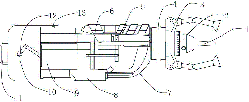
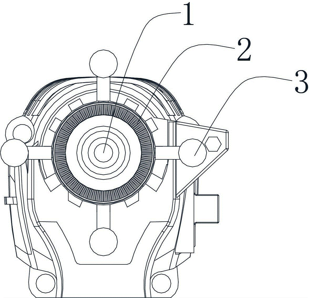
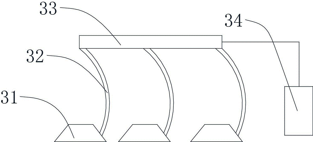
[0017] The arc-shaped part punching machine for construction includes a first housing 7, a drill chuck 2 is arranged at the front end of the first housing 7, a drill bit 1 is arranged inside the drill chuck 2, and the drill chuck 2 is provided with a drill bit 1. A mounting seat is provided on the chuck 2, and an annular positioning device 3 is provided on the mounting seat. The annular positioning device 3 includes a first contact arm and a second contact arm, and the first contact arm and the mounting seat Hinged, its lower end can be extended, the second contact arm is hinged with the first contact arm, the bottom is provided with a suction cup 31, the suction cup 31 is provided with a vacuum branch pipe 32, and the plurality of vacuum branch pipes 32 is connected to the vacuum main pipe 33, the end of the vacuum main pipe 33 is connected wi...


PUM


Abstract

A building circular arc component perforating machine comprises a first shell. A drill chuck is arranged at the front end of the first shell. A drill bit is arranged in the drill chuck. An installing base is arranged on the drill chuck. An annular positioning device is arranged on the installing base and comprises first touch arms and second touch arms. The first touch arms are hinged to the installing base, the second touch arms are hinged to the first touch arms, and suction cups are arranged at the bottoms of the second touch arms. A second shell is arranged at the tail of the first shell. The second shell is in sliding connection in the first shell. A crank is arranged in the second shell and drives a rocker, and the other end of the rocker is fixed to the first shell. The building circular arc component perforating machine has the following beneficial effects that no skidding exists when a component with a curved face is perforated, positioning is accurate, and the device is small, simple, easy to implement, convenient to carry and suitable for construction sites.

Description

technical field [0001] The invention belongs to the field of drilling machines, in particular to a drilling machine for arc-shaped parts used in construction. Background technique [0002] When machining architectural parts, in order to ensure the processing requirements, first find the corresponding position point on the part and determine its position on this plane, so that the parts to be processed will not be affected by external forces during the processing. The position changes, so it is necessary to use a fixture to tighten the parts to be processed. Some parts need to be drilled on the surface. The traditional drilling method uses a pistol drill to directly punch holes on the parts. This method of drilling is easier on flat parts. However, when punching holes on parts with curved surfaces, due to the curved surface structure, it is difficult for the staff to operate, the work efficiency is low, and the precision of the punched holes is not high, it is easy to slip, a...

Claims


Application Information

Patent Timeline
IPC IPC(8): B23B45/02B23B45/14
CPCB23B45/02B25H1/0021
Inventor 徐永春
Owner ZHEJIANG BUSINESS TECH INST
Why Eureka
Try Eureka