Full-automatic grinding machine applied to metal surface machining assembly line

An assembly line and fully automatic technology, applied in metal processing equipment, grinding racks, grinding machines, etc., can solve problems such as production errors, waste of manpower, and errors in manual operations, and achieve accurate counting, improve efficiency, and save manpower. Effect

Inactive Publication Date: 2016-01-27
TIANJIN ZHONGDING ALUMINUM IND CO LTD
View PDF0 Cites 4 Cited by
  • Summary
  • Abstract
  • Description
  • Claims
  • Application Information

AI Technical Summary

Problems solved by technology

[0002] Metal surface grinding is an essential link in metal processing. In order to improve the smoothness of metal surfaces, grinding is required after metal processing. Automation is widely used in modern society, and automatic assembly lines are also used in factories. Now in most factories, When the metal surface is polished, it is mostly manual operation, which is inefficient, wast

Method used


Image

  • Full-automatic grinding machine applied to metal surface machining assembly line

Examples


Embodiment 1

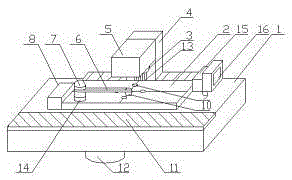
[0009] A full-automatic grinding machine applied to a metal surface processing line, comprising: an assembly line table 1, a grinding table 2, a grinding wheel 3, a guide rail mounting seat 4, a grinding wheel mounting seat 5, a rotating arm 6, a rotating shaft 7, and a rotating arm controller 8. Suction hole 9, small vacuum sucker 10, conveyor belt 11, vacuum generator 12, guide rail 13, rotating motor 14, controller 15, counter 16, a conveyor belt 11 is installed above the assembly line table 1, and a grinding table 2 is installed on one side of the conveyor belt 11. A suction hole 9 is provided on the grinding table 2, a vacuum generator 12 is installed below the suction hole 9, a rotating motor 14 is installed on one side of the grinding table 2, a rotating shaft 7 is installed above the rotating motor 14, a rotating arm 6 is installed above the rotating shaft 7, and one end of the rotating arm 6 is installed Small vacuum suction cup 10, arm controller 8 is installed on one...

Embodiment 2

[0011] The conveyor belt 11 sends the workpiece to the assembly line table top 1 and then stops. The rotating arm controller 8 controls the rotating motor 14 to run, so that the rotating arm 6 rotates. After the small vacuum chuck 10 reaches the top of the workpiece, it stops. The small vacuum chuck 10 runs to suck the workpiece. Stop, the rotating arm 6 rotates again to place the workpiece on the grinding table 2, the small vacuum suction cup 10 stops running, the rotating arm 6 resets, the controller 15 controls the operation of the vacuum generator 12, and the workpiece is fixed on the grinding table 2 through the suction hole 9 At the same time, the grinding wheel mounting seat 5 moves downward on the guide rail 13 to grind the workpiece. After grinding, the grinding wheel mounting seat 5 moves upward, the vacuum generator 12 stops running, the counter 16 counts once, and the rotating arm 6 rotates again to remove the workpiece from Take it out on the grinding table 2 and p...


PUM


Abstract

The invention relates to a full-automatic grinding machine applied to a metal surface machining assembly line. The full-automatic grinding machine comprises an assembly line table top, a grinding table and the like, and is characterized by further comprising a guide rail installing base, a rotating arm, a rotating shaft, a rotating arm controller, a suction hole, a small vacuum suction cup, a vacuum generator, a guide rail, a rotation motor, a controller and a counter; and a conveying belt is arranged above the assembly line table top, the grinding table is arranged on one side of the conveying belt, and the grinding table is provided with the suction hole. A workpiece is fixed through the vacuum generator and the suction hole, and a clamp is prevented from damaging the workpiece. The rotating arm controller can control the rotation motor to enable the rotating arm to rotate, the workpiece is sucked through the small vacuum suction cup, automatic feeding and discharging are achieved, labor is saved, and efficiency is improved. The controller controls a grinding wheel installing base to move on the guide rail, manual operation is not needed, and labor is saved. After one-time machining, the controller triggers the counter to carry out one-time counting, automatic counting of the counter is achieved, and counting is more accurate.

Description

technical field [0001] The invention relates to metal surface processing equipment, in particular to a fully automatic grinding machine applied to a metal surface processing line. Background technique [0002] Metal surface grinding is an essential link in metal processing. In order to improve the smoothness of metal surfaces, grinding is required after metal processing. Automation is widely used in modern society, and automatic assembly lines are also used in factories. Now in most factories, When the metal surface is polished, it is mostly manual operation, which is inefficient, wastes manpower, and is prone to errors; after grinding the workpiece, manual counting is also required, which is very prone to errors such as omissions and over-recording, resulting in errors in production; traditional During the grinding process, the workpiece needs to be clamped with a fixture, which is cumbersome to operate, and is easy to damage the workpiece, and the method is very backward. ...

Claims


Application Information

Patent Timeline
IPC IPC(8): B24B19/00B24B27/02B24B41/06B24B41/00B24B41/02
CPCB24B19/00B24B27/02B24B41/00B24B41/005B24B41/02B24B41/06
Inventor 张小磊
Owner TIANJIN ZHONGDING ALUMINUM IND CO LTD
Why Eureka
Try Eureka