Electricity receiving method and device for vehicles

An electrical method and vehicle technology, applied in the field of transportation, can solve the problems of low power feeding efficiency, difficulty in achieving stable power reception, and no method for obtaining signal type and signal duration information of the signal light system, so as to improve power feeding efficiency , stable power reception, and stable contact effect

Active Publication Date: 2016-01-27
刁心玺
View PDF14 Cites 1 Cited by
  • Summary
  • Abstract
  • Description
  • Claims
  • Application Information

AI Technical Summary

Problems solved by technology

[0016] The road-associated power supply network technology is a technical solution to be perfected for the sustainable driving of electric vehicles on the road. The current road-associated power supply technology and the contact road-associated power supply technology have the disadvantage that it is difficult to ensure the connection between the feeder line and the receiving brush. Stable contact; the disadvantage of non-contact power supply technology is that it is difficult to ensure the stability of the coupling distance between the power supply coil and the power receiving coil; thus making it difficult to achieve stable power reception and low feed efficiency;
[0017] The prior art does not propose the idea of ​​using the vehicle to receive power from the road-associated power supply network when the road traffic signal light is red, nor does it provide a method for obtaining the signal type and signal duration information output by the signal light system

Method used


Image

  • Electricity receiving method and device for vehicles
  • Electricity receiving method and device for vehicles
  • Electricity receiving method and device for vehicles

Examples


Embodiment 1

[0060] Embodiment 1, an example of a vehicle power receiving method

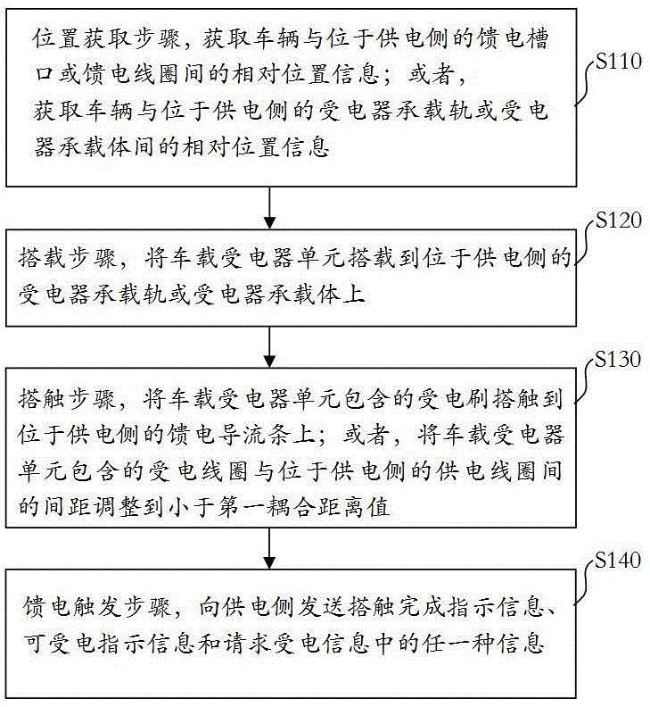
[0061] see figure 1 As shown, an example of a vehicle power receiving method in the embodiment provided by the present invention includes the following steps:

[0062] Step S110, the position acquisition step, acquires the relative position information between the vehicle and the feed slot or feed coil on the power supply side; or,

[0063] Obtain the relative position information between the vehicle and the receiver carrier rail or receiver carrier on the power supply side;

[0064] Step S120, the loading step, loading the on-board power receiver unit on the power receiver carrying rail or the power receiver carrier on the power supply side;

[0065] Step S130, touch step, touch the power receiving brush included in the on-board power receiver unit to the feed guide bar on the power supply side; or connect the power receiving coil included in the on-board power receiver unit to the power supply coil on th...

Embodiment 2

[0118] Embodiment 2, an example of a vehicle power receiving device

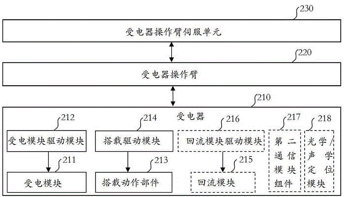
[0119] see figure 2 As shown, an example of a vehicle power receiving device in the embodiment provided by the present invention includes:

[0120] Power receiving module 211, power receiving module driving module 212, equipped with action parts 213, equipped with driving module 214;

[0121] The power receiving module 211 is used to obtain electric energy from the feeding guide bar arranged in the feeding slot cavity or on the lip of the feeding slot in a shielding manner on the power supply side, including: the receiving brush rotating joint assembly, the receiving brush brush;

[0122] The power receiving module driving module 212 is used to drive the power receiving module to complete the protruding of the power receiving brush from the cavity contained in the neck of the power receiver, the adjustment of the attitude of the power receiving brush, and the contact action between the power receiving bru...

Embodiment 3

[0186] Embodiment 3, an example of a vehicle power supply device

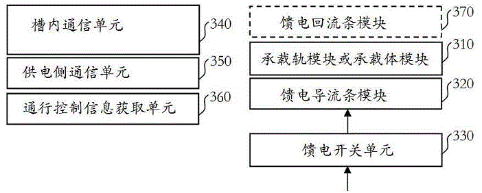
[0187] see image 3 As shown, an example of a vehicle power supply device in the embodiment provided by the present invention includes:

[0188] Receiver carrying rail or carrier module 310, feed guide bar module 320; optionally, feed return bar module 370;

[0189] The carrier rail or carrier module 310 is used to provide load for the receiver, including: receiver carrier rails or receiver bearing parts arranged on one side or both sides of the feed slot;

[0190] The feed guide bar module 320 is used to feed electric energy to the receiving brushes included in the receiver, including: at least one feed guide bar unit arranged in a shielding manner;

[0191] The feed return bar module 370 is used as a return channel for feeding power to the receiver, including: at least one feed return bar unit arranged in a shielding manner;

[0192] Wherein, the implementation of providing bearer for the receiver includes...


PUM


Abstract

The invention provides an electricity receiving method and device for vehicles. The electricity receiving method and device are used for overcoming at least one of the defects on the aspects of electricity receiving stability and electricity receiving efficiency. The electricity receiving method includes a position obtaining step, a carrying step, a touching step and a feed triggering step. The method and the device have at least one of the beneficial effects that stable contact between feed lines and electricity receiving brushes can be achieved; the coupling distance between a power supply coil and an electricity receiving coil is ensured to be stable; vehicles can receive electricity from a power supply network along a road when road traffic lights are red in a stable mode; the feed efficiency can be improved; and the practicability is achieved.

Description

technical field [0001] The present invention relates to the field of traffic, in particular to a method and device for receiving electricity from a vehicle. Background technique [0002] In order to solve the problem of insufficient cruising range of the vehicle-mounted power supply method for electric vehicles running on highways / roads, in the field of patent applications, there have been some technical solutions for implementing accompanying power supply for electric vehicles driving on highways / roads. In the published patent application, the technology of implementing accompanying power supply for electric vehicles running on roads / roads includes two basic schemes: contact accompanying power supply and non-contact accompanying power supply. [0003] The accompanying power supply technology for contact road / road driving electric vehicles includes three methods: road power supply, overhead power supply above the road surface and roadside power supply. [0004] Road power s...

Claims


Application Information

Patent Timeline
Patent Type & Authority Applications(China)
IPC IPC(8): B60M1/30B60L9/00G08G1/00B60L5/38B60L5/00
Inventor 刁心玺
Owner 刁心玺
Why Eureka
Try Eureka