Unmanned aerial vehicle body

A manufacturing method and unmanned aerial vehicle technology, which is applied to rotorcraft, motor vehicles, floats, etc., can solve problems such as insufficient endurance, blade damage, and large take-off weight, so as to achieve enhanced endurance and stability, and improve the overall structural strength , the effect of weight reduction

Active Publication Date: 2016-01-27
绍兴宝旌复合材料技术研发有限公司
View PDF7 Cites 19 Cited by
  • Summary
  • Abstract
  • Description
  • Claims
  • Application Information

AI Technical Summary

Problems solved by technology

The body of conventional drones is mostly made of metal materials such as steel and aluminum alloy, which has a large take-off weight and insufficient endurance; at the same time, the landing gear of conventional drones is mostly bracket type, skid type, etc. Landing gear is only suitable for landing on land or flat ground, with limited functions and narrow application fields; and during flight, the space environment is relatively complex, and the blades are easily damaged by impacts from solid garbage, birds and other unknown objects. Leaf damage will directly affect the flight effect of the entire UAV, which is not conducive to the normal operation of its work.

Method used


Image

  • Unmanned aerial vehicle body
  • Unmanned aerial vehicle body
  • Unmanned aerial vehicle body

Examples


Embodiment 1

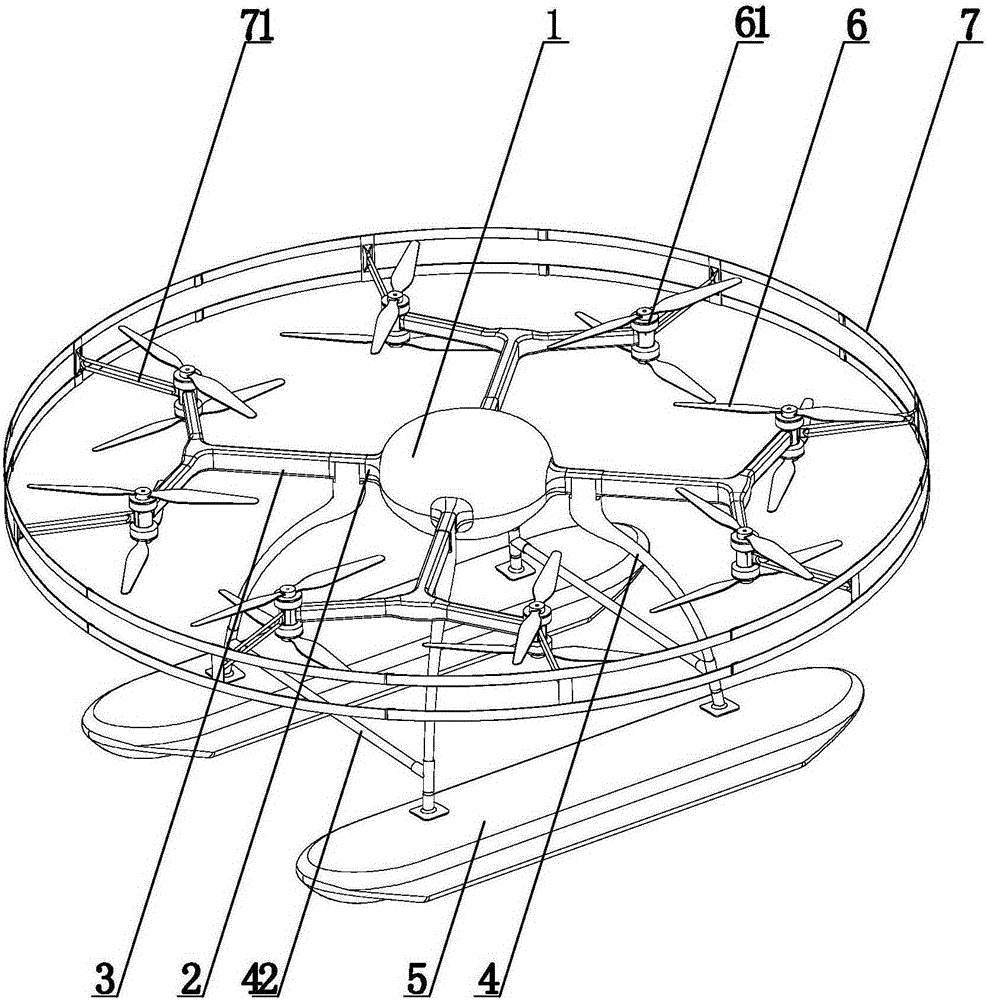
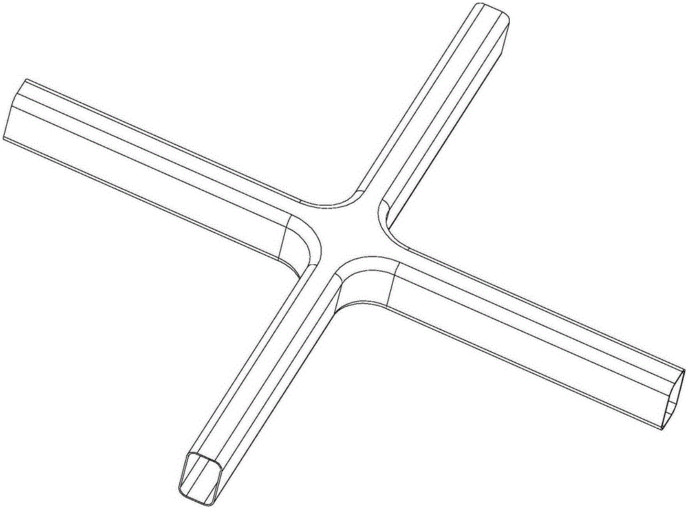
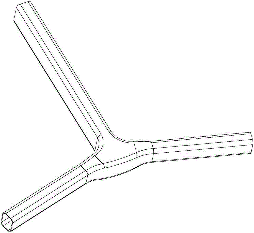
[0029] The drone body of this embodiment, combined with figure 1 , consists of cockpit 1, central support arm 2, cantilever 3, landing gear 4, buoys 5, rotor 6 and anti-collision ring 7, cockpit 1 is inside, anti-collision ring 7 is located outside the cockpit, buoys 5 are arranged in pairs, and are located at below the cockpit 1, which, combined with figure 2 , the central support arm 2 is provided with four, respectively symmetrically installed on the periphery of the cockpit 1, the central support arm 2 is a cross-shaped hollow structure; combined image 3 , each central support arm 2 corresponds to a cantilever 3, the cantilever 3 is a Y-shaped hollow structure, one end of the cantilever 3 is inserted into the central support arm 1, and the other two ends are connected to the inner periphery of the anti-collision ring 7 through the anti-collision support arm 71; The upper end of the landing gear 4 is connected with the central arm 2, and the lower end is fixed with the b...


PUM


Abstract

The invention relates to an unmanned aerial vehicle body, which belongs to the technical field of unmanned aerial vehicles. The unmanned aerial vehicle body comprises a cockpit, central supporting arms, cantilevers, landing frames, a buoys, rotor wings and an anti-collision ring, wherein the central supporting arms are mounted on the circumference of the cockpit; the central supporting arms are cross-shaped hollow structures; the cantilevers are Y-shaped hollow structures; one ends of the cantilevers are inserted into the central supporting arms and connected with the cockpit through the central supporting arms; the other two ends of the cantilevers are connected with the inner circumference of the anti-collision ring through anti-collision supporting arms; the upper ends of the landing frames are connected with the central supporting arms; the lower ends of the landing frames are fixed together with the buoys; and rotor wings driven by a motor is arranged on the cantilevers. The invention is applied to the manufacturing of unmanned aerial vehicle bodies and has the advantages of light mass, high strenght, amphibious property and the like.

Description

technical field [0001] The invention relates to a drone body and a manufacturing method thereof, belonging to the technical field of drone facilities. Background technique [0002] At present, drones are developing rapidly, resulting in multi-style and multi-purpose drones. The body of conventional drones is mostly made of metal materials such as steel and aluminum alloy, which has a large take-off weight and insufficient endurance; at the same time, the landing gear of conventional drones is mostly bracket type, skid type, etc. Landing gear is only suitable for landing on land or flat ground, with limited functions and narrow application fields; and during flight, the space environment is relatively complex, and the blades are easily damaged by impacts from solid garbage, birds and other unknown objects. Leaf damage will directly affect the flight effect of the entire UAV, which is not conducive to the normal operation of its work. [0003] Based on this, this application...

Claims


Application Information

Patent Timeline
Patent Type & Authority Applications(China)
IPC IPC(8): B64C27/08B64C25/54B64C27/20
Inventor 张卉梓王冠胡纪根戈家荣沈伟
Owner 绍兴宝旌复合材料技术研发有限公司
Why Eureka
Try Eureka