
Aluminum electrolysis cell leakage monitoring and alarming method

An aluminum electrolytic cell and drain tank technology, which is applied in the field of aluminum electrolytic cell drain tank monitoring and alarm, can solve the problems that the electrolytic cell cannot carry out electrolytic aluminum work, the output decreases, and the economic loss is large.

Inactive Publication Date: 2016-01-27
CHONGQING TECH & BUSINESS INST
View PDF7 Cites 4 Cited by
  • Summary
  • Abstract
  • Description
  • Claims
  • Application Information

AI Technical Summary

Problems solved by technology

[0002] In today's aluminum electrolysis industry, metal aluminum is obtained by electrolysis of alumina. When aluminum is electrolyzed, alumina is in the electrolytic cell, and the temperature in the electrolytic cell is very high, reaching thousands of degrees. Since the electrolytic cell is composed of a cathode and a refractory brick After a period of time, it will cause leakage in some places of the electrolytic cell
If there is a leakage tank, it will cause the electrolytic cell to not work normally and must be repaired. On the one hand, the electrolytic cell cannot perform electrolytic aluminum work, and the output will drop. On the other hand, due to the maintenance of the electrolytic cell, the economic loss will be relatively large; It may also lead to casualties of workers operating on site
Therefore, it is very important to be able to predict the leakage of the electrolytic cell online in real time in the electrolysis workshop. Since the temperature in the cell is as high as thousands of degrees during the electrolysis of aluminum, it is impossible to observe the leakage in real time from the inside of the electrolytic cell. Currently, there is no such An accurate and effective detection method for leakage of aluminum electrolytic cell

Method used


Image

  • Aluminum electrolysis cell leakage monitoring and alarming method
  • Aluminum electrolysis cell leakage monitoring and alarming method
  • Aluminum electrolysis cell leakage monitoring and alarming method

Examples


Embodiment Construction

[0028] Below in conjunction with accompanying drawing and embodiment the present invention will be further described:

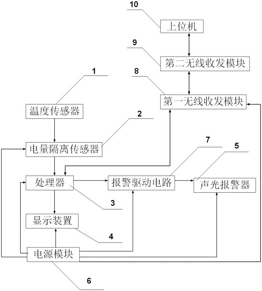
[0029] Such as figure 1 As shown, the wireless drain monitoring device includes a temperature sensor 1, an electrical isolation sensor 2, a processor 3, a display device 4, an audible and visual alarm 5, and a power supply module 6; the output end of the temperature sensor 1 is connected to the electrical isolation sensor 2, the output terminal of the electrical isolation sensor 2 is connected to the input terminal of the processor 3, the first output terminal of the processor 3 is connected to the input terminal of the display device 4, and the second output terminal of the processor 3 The output terminal is connected to the input terminal of the sound and light alarm 5 through the alarm driving circuit 7, and the processor 3 is bidirectionally connected with a first wireless transceiver module 8, and the first wireless transceiver module 8 communicates with...


PUM


Abstract

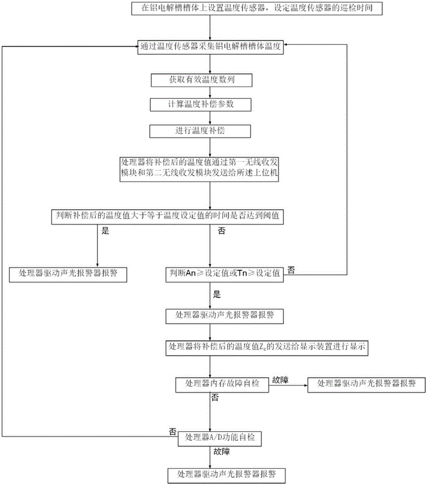
The invention discloses an aluminum electrolysis cell leakage detecting method based on a cell leakage monitoring device, and belongs to the field of aluminum electrolysis cell monitoring. The method dynamically compensates acquired temperature according to acquired aluminum electrolysis cell temperature values and aluminum electrolysis cell temperature variation trends, so that a system can accurately prejudge a temperature regulating quantity to effectively monitor the temperature in the aluminum electrolysis process, the leakage condition in each point of a cell body of the electrolysis cell can be more accurately and effectively monitored in real time, and the aluminum electrolysis quality is guaranteed; and meanwhile, as the influence of interference data is greatly eliminated, the adaptability of the temperature monitoring method in different aluminum electrolysis environments is guaranteed. The cell leakage condition can be effectively prevented through judging whether the time of the compensated temperature value not smaller than a set temperature value reaches a threshold value or not.

Description

technical field [0001] The invention belongs to the field of aluminum electrolytic cell monitoring, and in particular relates to a method for monitoring and alarming an aluminum electrolytic cell leak. Background technique [0002] In today's aluminum electrolysis industry, metal aluminum is obtained by electrolysis of alumina. When aluminum is electrolyzed, alumina is in the electrolytic cell, and the temperature in the electrolytic cell is very high, reaching thousands of degrees. Since the electrolytic cell is composed of a cathode and a refractory brick After a period of time, it will cause leakage in some places of the electrolytic cell. If there is a leakage tank, it will cause the electrolytic cell to not work normally and must be repaired. On the one hand, the electrolytic cell cannot perform electrolytic aluminum work, and the output will drop. On the other hand, due to the maintenance of the electrolytic cell, the economic loss will be relatively large; It may als...

Claims


Application Information

Patent Timeline
IPC IPC(8): C25C3/20
Inventor 廖妍
Owner CHONGQING TECH & BUSINESS INST
Learn More