

Leakage stopping device for subsea production
A plugging device and oil production well technology, which is applied in earthwork drilling, wellbore/well components, sealing/isolation, etc., can solve the problems of high cost, cumbersome operation, long plugging time, etc., and achieve low cost, Simple operation, fast plugging effect
- Summary
- Abstract
- Description
- Claims
- Application Information
AI Technical Summary
Problems solved by technology
Method used
Image

Examples
Embodiment Construction
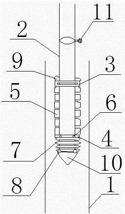
[0013] Accompanying drawing is a kind of specific embodiment of the present invention. This embodiment includes an oil well 1 and a tubing 2. The lower part of the tubing 2 is provided with an upper expansion rubber control ring 3 and a lower expansion rubber control ring 4 respectively, and an expansion sponge is arranged between the upper expansion rubber control ring 3 and the lower expansion rubber control ring 4. 5. The lower expansion rubber control ring 4 is connected to the spring 7 through the upper spring controller 6, and the spring 7 is fixed to the bottom of the oil pipe 2 through the lower spring controller 8. Anti-slip sand 9 is provided between the upper expansion rubber control ring 3 and the oil pipe 2 . A decompression head 10 is installed at the bottom of the oil pipe 2 . A valve 11 is installed at the lower part of the oil pipe 2 protruding from the oil well 1 .
[0014] Using the plugging device for underwater oil production wells of the present inventi...
PUM
 Abstract
Description
Claims
Application Information