Coupler

A technology of couplings and shaft sleeves, which is applied in the field of couplings that are easy to adjust and balance, can solve the problems of low efficiency of coupling balance tests, achieve the effects of reducing times, improving precision, and improving practical performance

Inactive Publication Date: 2016-01-27
SICHUAN YOUKE COMM TECH
View PDF7 Cites 3 Cited by
  • Summary
  • Abstract
  • Description
  • Claims
  • Application Information

AI Technical Summary

Problems solved by technology

[0004] In order to solve the problem of low efficiency of the balance test of the existing coupling, the present invention provides a

Method used


Image

  • Coupler
  • Coupler

Examples


Embodiment Construction

[0017] The present invention will be further described below in conjunction with the embodiments, and the described embodiments are only a part of the embodiments of the present invention, not all of them. Based on the embodiments of the present invention, other used embodiments obtained by persons of ordinary skill in the art without creative efforts all belong to the protection scope of the present invention.

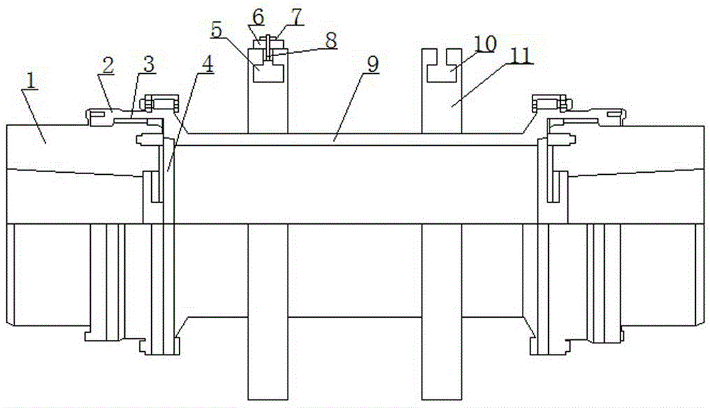
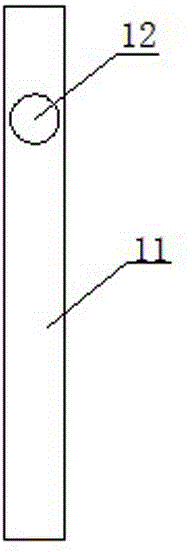
[0018] The coupling of the present invention includes a shaft sleeve, an end cover, an inner ring gear, a gland, and an intermediate connecting pipe. Both ends of the intermediate connecting pipe are symmetrically provided with balance rings, and the balance ring is sleeved on the outer wall circumference of the intermediate connecting pipe. , the balance ring is provided with an annular installation groove along the outer circumferential direction, the section of the installation groove along the radial direction is in the shape of a "convex", and the installation gro...


PUM


Abstract

The invention discloses a coupler. The coupler comprises a shaft sleeve, an end cover, an inner gear ring, a gland and a middle connecting pipe. The two ends of the connecting pipe are symmetrically provided with balance rings which are arranged on the circumference of the outer wall of the middle connecting pipe in a sleeving manner; the balance rings are provided with annular installing grooves in the peripheral direction; the cross sections of the installing grooves in the radial direction are in the shape of inverted T; the installing grooves are evenly provided with balance block inlets in the radial direction of the installing grooves; the shapes of balance blocks are the same as those of the cross sections of the installing grooves, and the balance blocks are in the shape of inverted T; the balance blocks can slide annularly along the installing grooves; threaded rods are arranged at the top ends of the balance blocks which are provided with fastening blocks; and the threaded rods penetrate the fastening blocks and are fixedly connected with nuts. The balance test efficiency of the coupler can be improved.

Description

technical field [0001] The invention relates to a shaft coupling, in particular to a shaft coupling which is convenient for adjusting balance. Background technique [0002] Couplings are an indispensable link in mechanical transmission. It is mainly used to connect the driving shaft and the driven shaft, to transmit motion and torque, and to compensate for the influence of uneven material structure, manufacturing error, installation error, deformation after loading and temperature changes between the two, so that The main inertial axis passing through the center of mass of the coupling does not coincide with the axis of rotation. A small eccentricity of the coupling will generate a large centrifugal inertial force, which will generate a large additional dynamic pressure on the bearing. It not only makes the shaft and The working condition of the bearing deteriorates, and because the magnitude and direction of the centrifugal inertial force generally change periodically, it ...

Claims


Application Information

Patent Timeline
IPC IPC(8): F16D3/18F16F15/34G01M1/32G01M1/02
Inventor 方远兵郑俊杰唐福生
Owner SICHUAN YOUKE COMM TECH
Why Eureka
Try Eureka