In-pipe walking robot

A walking robot and walking mechanism technology, applied in the direction of special pipes, pipe components, mechanical equipment, etc., can solve problems such as unfavorable robot maintenance operations, increase robot load, and affect robots, so as to facilitate pipeline construction operations and subsequent robot maintenance operations , The mechanical connection relationship is simple and the effect of ensuring synchronization

Active Publication Date: 2016-01-27
S Z VICTOR AUTOMATION TECH
View PDF7 Cites 20 Cited by
  • Summary
  • Abstract
  • Description
  • Claims
  • Application Information

AI Technical Summary

Problems solved by technology

[0005] The above-mentioned pipeline spraying robot adopts manual adjustment of the handwheel to adjust the distance between the rollers. After the robot enters the pipeline operation, the distance between the rollers is set to a fixed state, which is suitable for internal operations in pipelines with little change in pipe diameter, especially for straight pipe operations; in addition, for each The (group) rollers are equipped with corresponding deceleration motors. The spraying robot is equipped with at least four deceleration motors. This will undoubtedly increase the load on the robot, which is not conducive to the flexible operation of the robot. On the other hand, the probability of failure of multiple motors will also increase. If a motor fails, it will cause a certain (group) of rollers to fail to roll, and the force between the entire robot and the inner wall of the pipeline will be uneven, which will even affect the robot's inability to work; moreover, the design of its walking mechanism is relatively complicated, which is not conducive to subsequent robot maintenance operations

Method used


Image

  • In-pipe walking robot
  • In-pipe walking robot
  • In-pipe walking robot

Examples


Embodiment Construction

[0039] The invention will be described in detail below in conjunction with the accompanying drawings and specific embodiments.

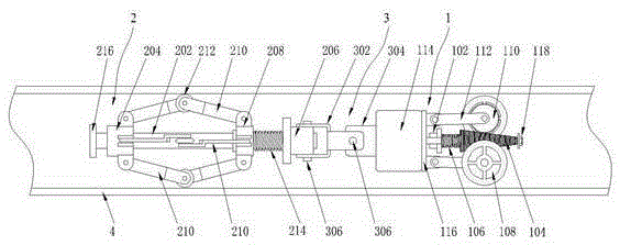
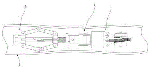
[0040] see Figure 1 to Figure 5 , the present invention provides a walking robot in a pipeline, including a walking mechanism 1, a connecting rod assembly 2, and a universal connection mechanism 3;

[0041] Described walking mechanism 1 comprises:

[0042] A transmission mechanism, which is provided with an output shaft, the output shaft is fixed with a shaft connector 102, and a coaxial and freely sliding worm 104 is nested on the shaft connector 102, the side of the worm 104 is an arc surface, and the shaft The end of the connector 102 away from the transmission mechanism is provided with an anti-slip component; and

[0043] A first pressure spring 106, nested on the output shaft, is located between the shaft connector 102 and the worm 104; and

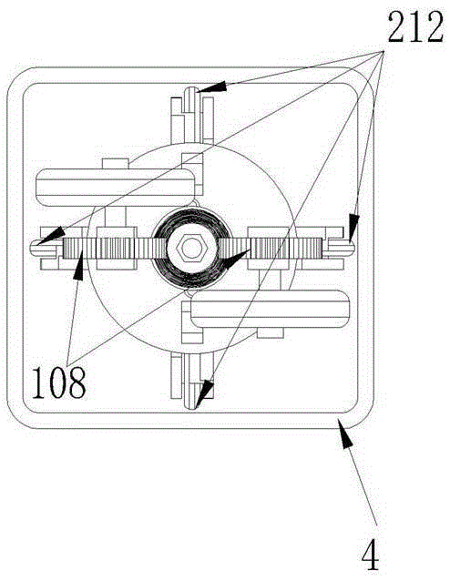
[0044] Two traveling wheels 108, each traveling wheel 108 is connected with a worm wheel 110 which ...


PUM


Abstract

The invention discloses an in-pipe walking robot. The in-pipe walking robot comprises a running mechanism, a connecting rod assembly and a universal connecting mechanism connected with the running mechanism and the connecting rod assembly. The running mechanism comprises a transmission mechanism, a first pressure spring, two road wheels and two rocker connecting rods. The connecting rod assembly comprises a center rod, a front locking block, a rear locking block, a sliding block, at least two pairs of connecting rod slices, at least two pulleys and a second pressure spring. According to the in-pipe walking robot, the synergistic effect of worm gears, a worm and the first pressure spring is adopted, the close fit of the worm gears and the worm is retained, and the road wheels are made to roll on the inner wall of a pipe in a tightly attached mode. When the worm is in a shape of a taper or a circular truncated cone, the running mechanism can automatically adjust the interval of the worm gears in pipes with different diameters, so that the road wheels are ensured to make contact with the inner wall of the pipe all the time and the adhesive force is retained; due to the second pressure spring, the symmetrical pulleys are always pushed by the sliding block to make contact with the inner wall of the pipe, so that a flange plate is ensured to be positioned on the central axis of the pipe all the time, and an operating mechanism externally connected with the flange plate can run with the flange plate steadily.

Description

technical field [0001] The invention belongs to the field of pipeline operation robots, and in particular relates to a walking robot in a pipeline, whereby the walking robot can carry various in-pipeline operation functions such as rust removal, spraying, and maintenance. Background technique [0002] In the national economic life, a large number of pipelines are used for the transportation of fuel oil, natural gas, drinking water, etc., which are closely related to people's lives. [0003] In pipeline operations, in order to enhance its anti-corrosion performance, the inner and outer walls are often sprayed. Mature spraying processing equipment can be used for the outer wall spraying, while the inner wall spraying is limited by the diameter of the pipeline, so there are not many available methods; for the later maintenance of pipelines Maintenance, such as rust removal, checking for cracks, etc., existing equipment is often stretched. [0004] In order to solve the problem...

Claims


Application Information

Patent Timeline
Patent Type & Authority Applications(China)
IPC IPC(8): F16L55/32F16L101/12F16L101/16F16L101/30
CPCF16L55/32F16L2101/12F16L2101/16F16L2101/30
Inventor 李维峰刘明昌张新华
Owner S Z VICTOR AUTOMATION TECH
Why Eureka
Try Eureka