
Dehumidifier

A dehumidifier and water tank technology, applied in defrosting, mechanical equipment, separation methods, etc., can solve the problems of small capacity, inconvenience, and insufficiently compact space structure, and achieve the effect of minimizing space loss and stable use.

Active Publication Date: 2016-01-27
LG ELECTRONICS INC
View PDF13 Cites 13 Cited by
  • Summary
  • Abstract
  • Description
  • Claims
  • Application Information

AI Technical Summary

Problems solved by technology

[0011] However, in the above-mentioned structure, in order to make it rotate without interference in the state where the water bucket is installed, the capacity of the part that can only be used to collect water becomes small, or it is necessary to have a Make the space for the bucket to rotate without interference, which will cause the problem that the space structure is not compact enough
[0012] And, when the above-mentioned water bucket is filled with water, when the water bucket is rotated and operated, since there is no other restrictive structure, it will cause the problem that the water bucket is easy to fall over or the operation is inconvenient.

Method used


Image

  • Dehumidifier
  • Dehumidifier
  • Dehumidifier

Examples


Embodiment Construction

[0054] Hereinafter, specific embodiments of the present invention will be described in detail with reference to the drawings. However, the present invention is not limited to the embodiment suggested by the technical idea of ​​the present invention, but can easily suggest other inventions that are backward or belong to the scope of the technical idea of ​​the present invention through the addition, modification, deletion, etc. of other structural elements. other examples within.

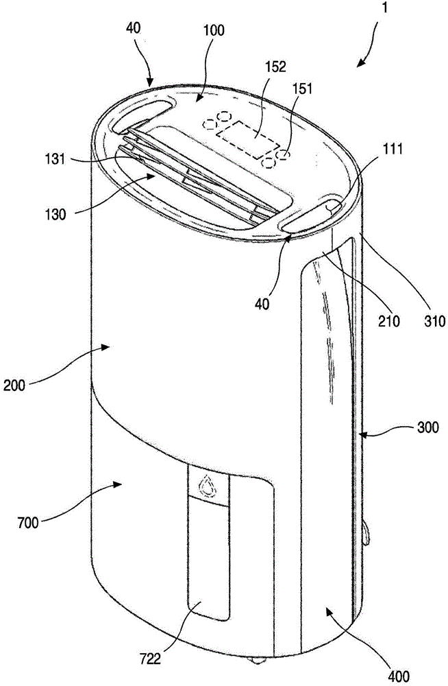
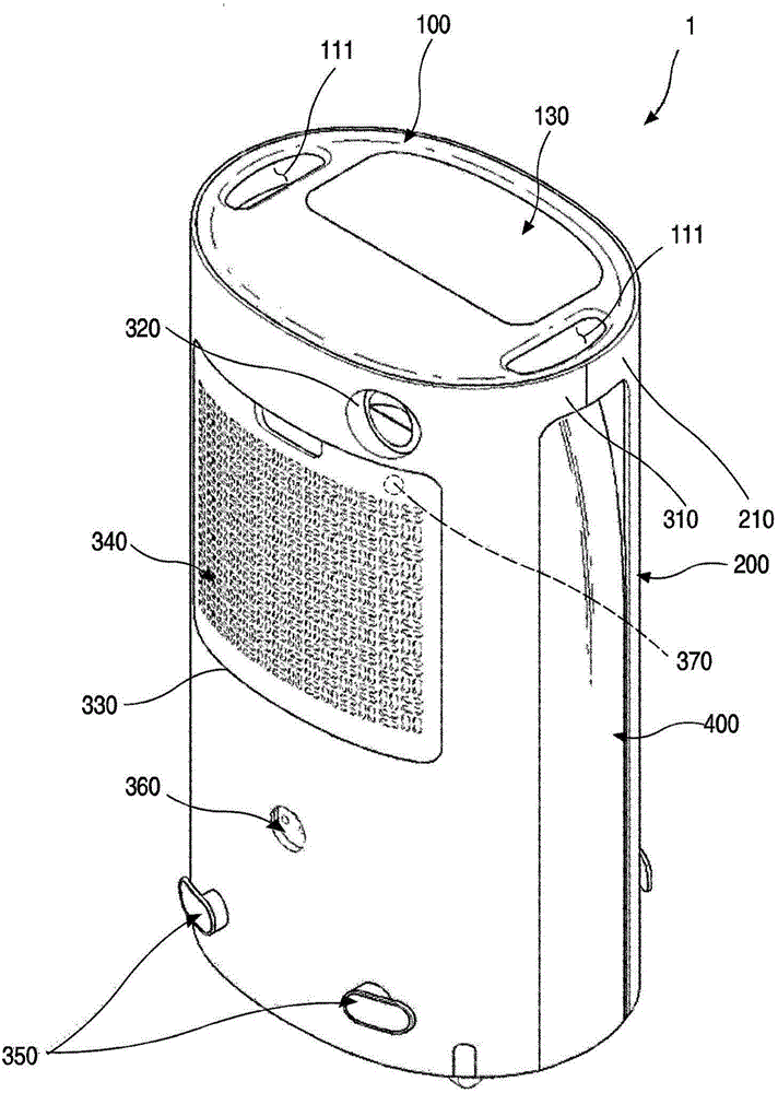
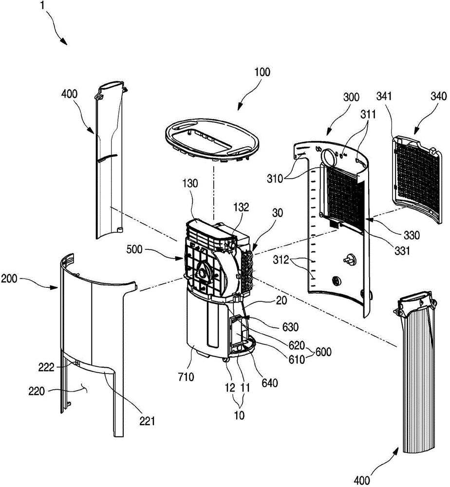
[0055] figure 1 It is a front perspective view of a dehumidifier according to an embodiment of the present invention, figure 2 It is the rear perspective view of the above dehumidifier, image 3 It is an exploded perspective view of the above-mentioned dehumidifier.

[0056] As shown in the figure, the main body of the dehumidifier 1 according to the embodiment of the present invention may have an elliptical cross-section as a whole when viewed from above, and may be formed in a barrel shape with...


PUM


Abstract

Provided is a dehumidifier 1 in which a tank drawer for accommodating a water tank is slidably inserted / withdrawn and tilted to easily withdraw the water tank in which condensed water is collected.

Description

technical field [0001] The invention relates to a dehumidifier. Background technique [0002] Usually, a dehumidifier is a kind of humid air that sucks the indoor space into the inside of the shell, and makes the above humid air pass through a heat exchanger composed of a condenser and an evaporator flowing with a refrigerant to reduce the humidity, and then re-introduces the humid air to the room. A device that discharges dehumidified air from the space to reduce indoor humidity. [0003] That is, the dehumidifier uses a method of evaporating liquid refrigerant in the evaporator to take heat from the surrounding air. As the refrigerant evaporates, the temperature of the evaporator drops, and the temperature of the air passing through the evaporator also increases the decline. Therefore, as the temperature around the evaporator drops, moisture contained in the air is condensed to form dew on the surface of the evaporator, and the dehumidified air is discharged indoors, the...

Claims


Application Information

Patent Timeline
IPC IPC(8): F24F3/14F24F1/02
CPCF24F3/14F24F2003/144F24F1/022F24F1/04F24F3/1405F24F13/20F24F2003/1446B01D53/265A47B81/00F16H19/04F25D21/14
Inventor 李建荣尹相渊李钟洙
Owner LG ELECTRONICS INC
Learn More