
GEO-UAV Bi-SAR route planning method based on differential evolution

A GEO-UAV, path planning technology, applied in the field of radar, can solve the problem that bistatic SAR path planning cannot be applied, and UAV imaging performance is not considered.

Inactive Publication Date: 2016-01-27
UNIV OF ELECTRONIC SCI & TECH OF CHINA
View PDF1 Cites 16 Cited by
  • Summary
  • Abstract
  • Description
  • Claims
  • Application Information

AI Technical Summary

Problems solved by technology

However, the above methods do not consider the imaging performance of UAV as a bistatic SAR receiving station, so they cannot be applied to the path planning problem of GEO-UAV bistatic SAR.

Method used


Image

  • GEO-UAV Bi-SAR route planning method based on differential evolution
  • GEO-UAV Bi-SAR route planning method based on differential evolution
  • GEO-UAV Bi-SAR route planning method based on differential evolution

Examples


Embodiment Construction

[0072] Embodiments of the present invention will be further described below in conjunction with the accompanying drawings.

[0073] The present invention mainly uses the method of simulation experiment to verify, and all steps and conclusions are verified by simulation in Matlab2013.

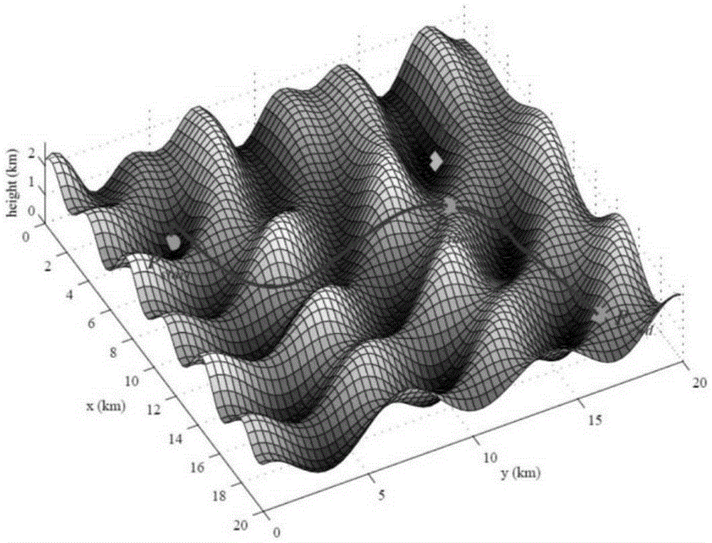
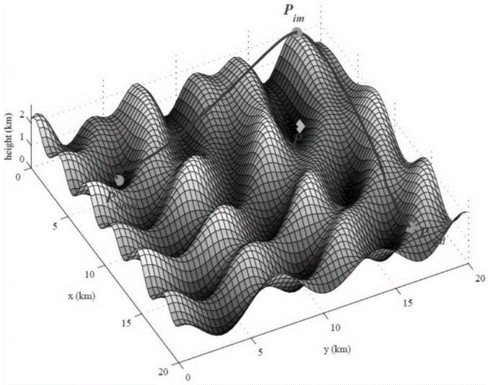
[0074] Step 1: Generate 3D simulated terrain according to formula (1). In order to simulate the real terrain height and surface, the following terrain parameters are selected: a, b, e, g=1, c, d, f=1.8. The two-dimensional grid spacing of the terrain is 0.2km, and the total length is 20km. Then the terrain height information matrix is ​​expressed as Z(x,y).

[0075] Step 2: Path modeling of UAV receiving station. According to formula (2), the UAV receiving station path is modeled as a set of control point coordinates, x=((x 1 ,y 1 ,z 1 ),(x 2 ,y 2 ,z 2 ),...,(x n ,y n ,z n )), in the simulation analysis, set the number n of UAV path control points to 9, where the first point is the s...


PUM


Abstract

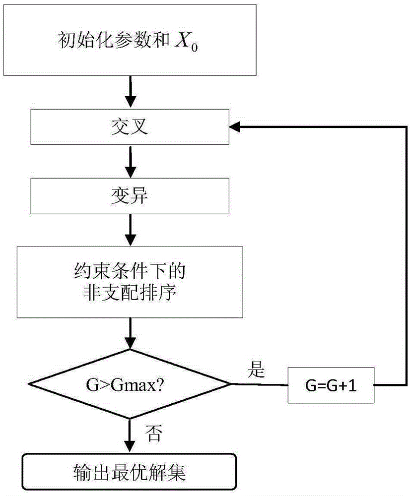
The invention discloses a GEO (Geosynchronous orbit)-UAV (unmanned aerial vehicle) Bi-SAR (synthetic aperture radar) route planning method based on differential evolution. The GEO-UAV Bi-SAR route planning method based on differential evolution comprises 1) generating a three dimensional landform; 2) modeling a UAV accepting station route; 3) modeling the route planning as a multiobjective optimization problem for a constraint condition; 4) utilizing a multiobjective differential evolution algorithm to solve; and 5) obtaining the optimal solution, generating a UAV optimal path, and realizing autonomous navigation and Bi-SAR imaging of the UAV in the three dimensional complicated landform. The GEO-UAV Bi-SAR route planning method based on differential evolution models the UAV route planning problem which comprehensively considers the route length, the flight safety and the SAR imaging performance as a multiobjective optimization problem, and utilizes the improved differential evolution algorithm to solve and obtain a set of optimal UAV accepting station flight routes.

Description

technical field [0001] The invention belongs to the technical field of radar, and in particular relates to a UAV receiving station flight path planning method for GEO-UAV bi-base SAR. Background technique [0002] Synthetic Aperture Radar (SAR) is an all-weather, all-weather high-resolution imaging system. It transmits a large time-width product chirp signal and receives a pulse compression signal through matched filtering to obtain high resolution in the range direction. Using synthetic aperture technology to achieve high resolution in azimuth, the imaging quality is not affected by weather conditions (clouds, light), etc., and has the characteristics of detecting and locating long-distance targets. [0003] Compared with LEO SAR, Geosynchronous Orbit Synthetic Aperture Radar (GEO-SAR) has a larger mapping bandwidth and shorter revisit period, which makes it widely used in disaster monitoring, tectonic imaging and other fields. Using GEO-SAR satellites as radiation sources...

Claims


Application Information

Patent Timeline
IPC IPC(8): G06Q10/04
Inventor 武俊杰孙稚超安洪阳杨建宇黄钰林杨海光杨晓波李财品李东涛
Owner UNIV OF ELECTRONIC SCI & TECH OF CHINA
Learn More