
Stent

A cylindrical, split-body technology, applied in the field of stents, can solve the problems of stents being unable to resist compressive force, insufficient structural stability, and reduced rigidity, and achieve excellent adaptability, avoid irregular deformation, and prevent irregular deformation.

Active Publication Date: 2016-01-27
TOKAI UNIV +1
View PDF7 Cites 0 Cited by
  • Summary
  • Abstract
  • Description
  • Claims
  • Application Information

AI Technical Summary

Problems solved by technology

However, in such a structure, although the flexibility of the stent in the torsional direction is enhanced, the structural stability may be insufficient due to the reduced rigidity in the axial direction, which may make the stent unable to resist the shaft. Compressive force in the direction, etc., resulting in such as Figure 17 Irregular plastic deformation shown

Method used


Image

  • Stent
  • Stent
  • Stent

Examples


Embodiment Construction

[0054] Embodiments of the present invention will be described below with reference to the drawings.

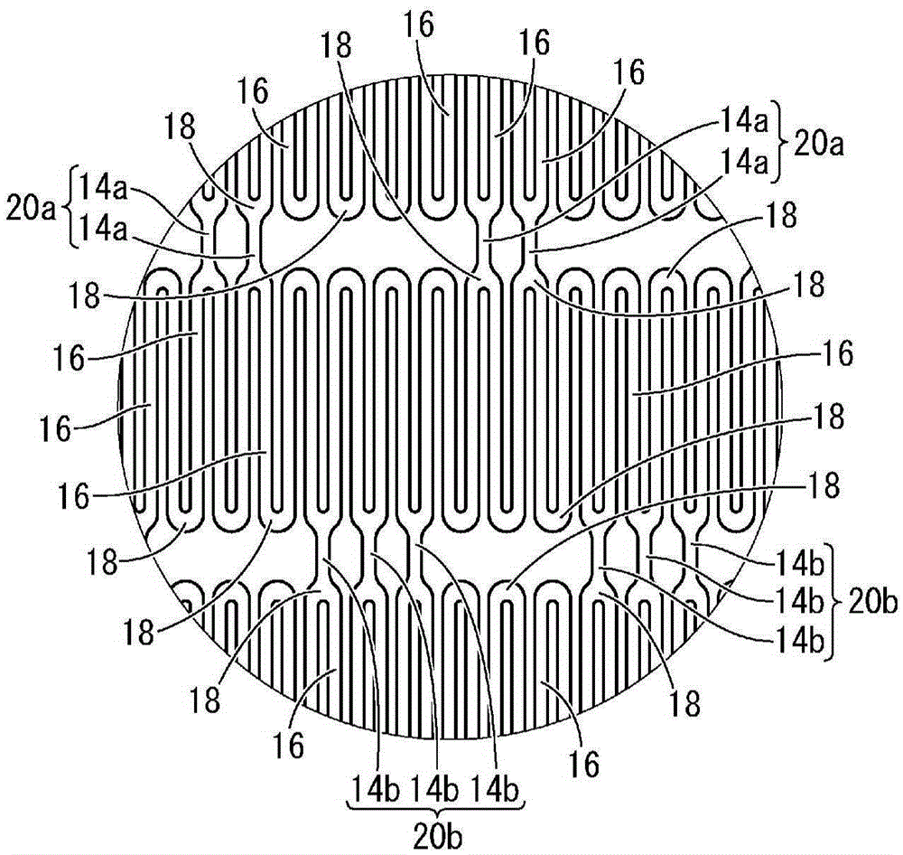
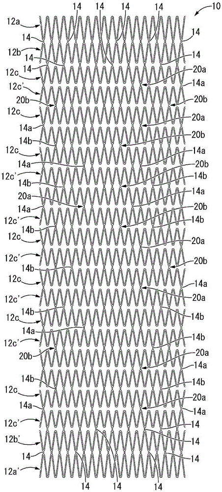
[0055] figure 1 The stent 10 is shown in a reduced-diameter state before expansion as a first embodiment of the present invention. The stent 10 having an approximately cylindrical shape as a whole has a structure in which a plurality of cylindrical divided bodies 12 are arranged in the axial direction, and the plurality of cylindrical divided bodies 12 are connected to each other by a connecting portion 14 .

[0056] In more detail, the cylindrical divided body 12 is provided with a plurality of linear portions 16 arranged at equal intervals on the periphery. Such as figure 2 As shown, the linear portion 16 is in the form of an elongated plate extending almost linearly in the axial direction, and a plurality of linear portions 16 are arranged at given intervals in the circumferential direction.

[0057] Also, the linear portions 16 adjacent to each other are connected to ...


PUM


Abstract

Provided is a stent having a novel structure, the stent simultaneously having both the stability of shape against the action of external force, such as compression force, tensile force, or torsional force, and high flexibility in the direction of twisting of the stent. Connection groups (20) are provided at three or more positions set at circumferentially equally-spaced intervals, the connection groups (20) each comprising connection sections (14) which are disposed circumferentially close to each other between axially adjacent cylindrical divided bodies (12c). The connection groups on both sides axially of each of the cylindrical divided bodies (12c) are provided at positions circumferentially offset from each other while at least one bend (18) is present between the connection groups.

Description

technical field [0001] The present invention relates to stents, which are implanted in body lumens, such as blood vessels, to maintain the internal diameter of the body lumens sufficiently large. Background technique [0002] There have been cases where stents have been implanted to push against the walls of the lumen and keep them in an expanded state, preventing restenosis with a device consisting of an external catheter that holding the stent at its tip; and an inner piston which pushes the stent forward after expanding the stent. For example, as disclosed in Japanese Patent JP-B-4703798 (Patent Document 1), the stent includes: a plurality of cylindrical divided bodies at a given distance from each other in the axial direction Arrangement; a plurality of connecting portions, through which the split bodies axially adjacent to each other are connected to each other. Further, the cylindrical divided body includes a plurality of linear portions arranged at almost equal inte...

Claims


Application Information

Patent Timeline
Patent Type & Authority Applications(China)
IPC IPC(8): A61F2/915
CPCA61F2/915A61F2002/91558A61F2002/91575A61F2002/91583A61F2002/825A61F2230/0054A61F2250/0018A61F2/89
Inventor 伊苅裕二松本邦晃
Owner TOKAI UNIV
Learn More