Gas-liquid baffle separation device

A liquid separation and gas flow technology, which is applied in the field of devices for baffled separation of gas-liquid two-phase flow, can solve the problems of affecting separation efficiency, separation method and single application field.

Inactive Publication Date: 2016-02-03
LUOYANG CHENXIANG MACHINERY TECH CO LTD
View PDF6 Cites 0 Cited by
  • Summary
  • Abstract
  • Description
  • Claims
  • Application Information

AI Technical Summary

Problems solved by technology

In order to solve the problem of single separation mode and application field of the existing gas-liquid separator, especially for the problem that the gas-liquid separator is affected by the entrainment of liquid droplets in the gas flow and the separation efficiency is affected, a gas-liquid separator with a corrugated channel is provided. Improve the separation efficiency based on the corrugation method, which can be applied in many fields

Method used


Image

  • Gas-liquid baffle separation device
  • Gas-liquid baffle separation device

Examples


Embodiment

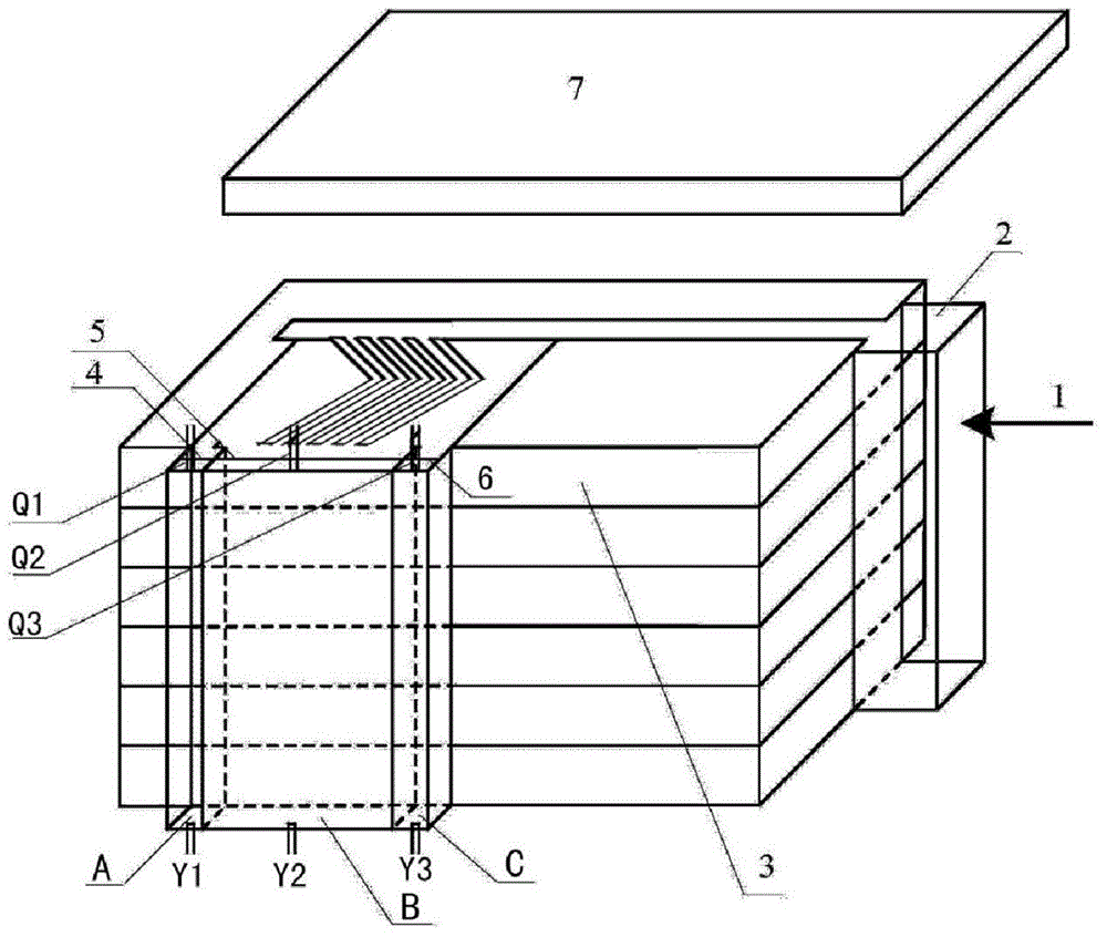
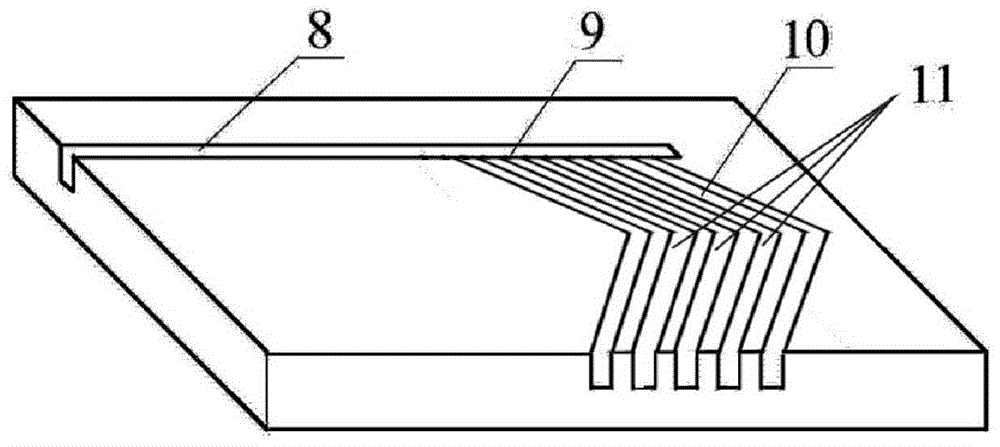
[0011] figure 1 is a schematic diagram of the baffled gas-liquid separation device of the present invention, figure 2 is a structural schematic diagram of the separator of the present invention, such as Figure 1 to Figure 2 shown. The baffle gas-liquid separation device of the present invention comprises a gas-liquid input port 1, an inlet distribution chamber 2, a pre-separator, a protection plate 7, and a separation chamber;

[0012] The above separation chambers include separation chamber A, separation chamber B, and separation chamber C. The upper end of each separation chamber is respectively provided with gas phase separation outlets Q1, Q2, Q3, and the lower end is respectively provided with liquid phase separation outlets Y1, Y2, Y3; wherein, the pre-separator is formed by stacking multiple partitions 3, and each partition 3 is provided with a main channel 8 of the input port and a plurality of sub-channels communicated with the above-mentioned main channel 8; each...


PUM


Abstract

A gas-liquid baffle separation device comprises an input control room, a pre-separator, a protection plate, separation rooms and the like, wherein the pre-separator comprises a plurality of layers of partitions which are piled up; a main inlet chute and a plurality of sub-chutes are formed in each partition; a gas-liquid mixture is assigned by the input control room to the main inlet chutes of all the partitions, droplet entrainment in air flow disappears, and liquid phases are uniformly distributed in the form of a liquid membrane along the circumferences of all the main inlet chute to form annular flow; after the annular flow passes through the sub-chutes of all the partitions, the liquid phases gather in two sub-chutes which are formed in the head and tail parts respectively, and gas phases gather concentrated in the middle sub-chutes for gas-liquid pre-separation; after the gas-liquid pre-separation is finished, gas and a liquid are separately connected into the three separation rooms for separation again. Through adoption of the device, efficient gas-liquid separation is achieved.

Description

technical field [0001] The technical field of physical micromachining of the present invention particularly relates to a device for baffle-separating gas-liquid two-phase flow. Background technique [0002] The separation of gas-liquid two-phase flow is mainly carried out in the gas-liquid separator, and the gas-liquid separator adopts many separation structures, including gravity sedimentation, baffle separation, centrifugal separation, screen separation, ultrafiltration separation, packing separation, etc. . However, there are only two separation principles in combination. First, the mixture is separated by utilizing the difference in the quality (weight) of the components. The density of gas and liquid is different, the mass of gas is less than the mass of liquid under the same volume. Furthermore, the mixture is separated by utilizing the difference in particle size of the dispersion system. The molecular aggregation state of the liquid is different from that of the g...

Claims


Application Information

Patent Timeline
IPC IPC(8): B01D45/06B01D45/08
Inventor 张春辉王胜利
Owner LUOYANG CHENXIANG MACHINERY TECH CO LTD
Why Eureka
Try Eureka