
Compound hardware die

A hardware and mold technology, applied in the field of composite hardware molds, can solve the problems of difficult mold work, heavy workload, and inability to adjust the stamping stroke of the mold, and achieve the effect of simple installation workload, long practical life, and simple mold matching

Inactive Publication Date: 2016-02-03
WUJIANG XINTA FORWARD HARDWARE FACTORY
View PDF9 Cites 3 Cited by
  • Summary
  • Abstract
  • Description
  • Claims
  • Application Information

AI Technical Summary

Problems solved by technology

[0006] 1. The installation is complicated and the workload is heavy, and the work of mold matching is difficult, and it is difficult to accurately mold the mold, resulting in damage to the mold, which is not conducive to efficient production; moreover, accurate positioning cannot be achieved for materials of various sizes, and the precision of traditional molds can only achieve a tolerance of 1mm. Material loss is 2%, which is not conducive to cost reduction
[0007] 2. When the product to be stamped is mis-delivered or the height of the product to be stamped changes, the stamping stroke of the mold cannot be adjusted, resulting in poor consistency of the stamped product or damage to the mold, and the practical life of the mold is low

Method used


Image

  • Compound hardware die

Examples


Embodiment Construction

[0028] The present invention will be further described in detail below in conjunction with the accompanying drawings and specific preferred embodiments.

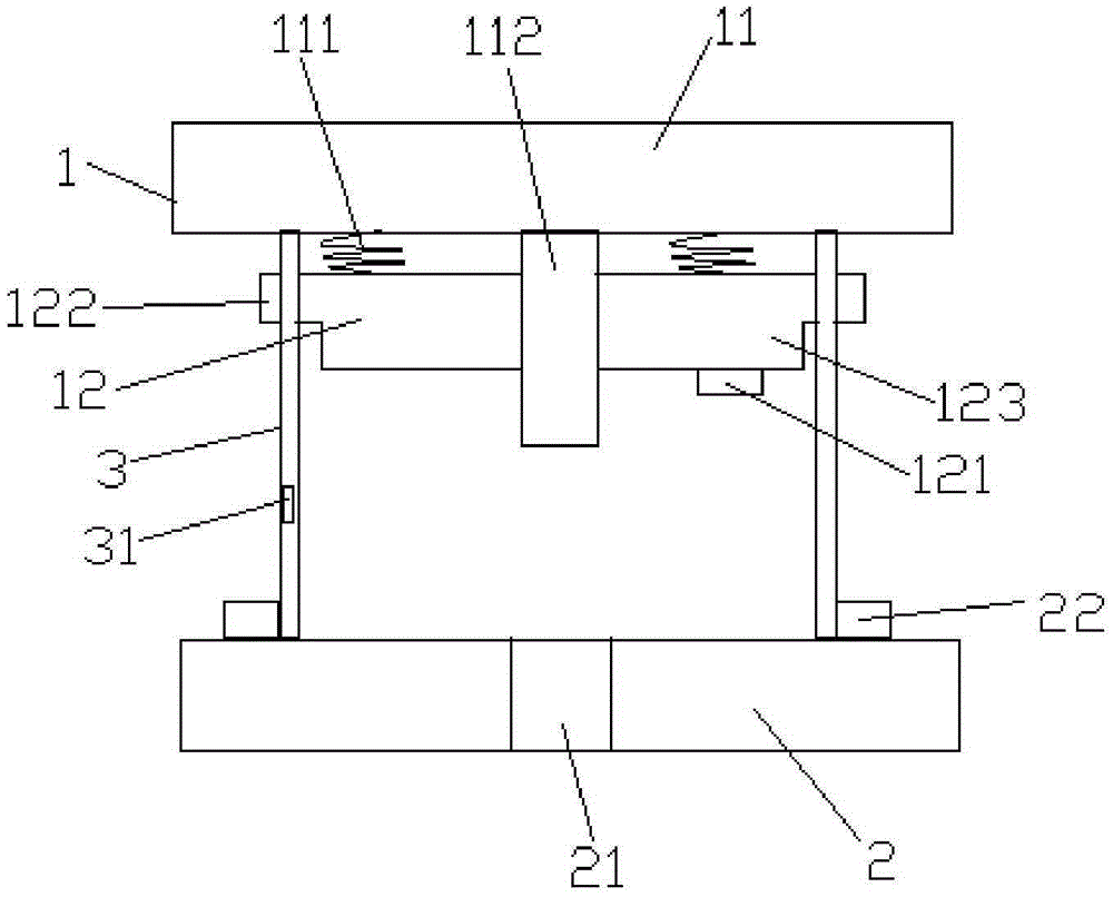
[0029] like figure 1 As shown, a composite metal mold includes an upper mold 1 , a lower mold 2 and a lifting guide post 3 .

[0030] The upper mold includes a hardware mold and an etching mold, wherein the etching mold is coaxially arranged between the hardware mold and the lower mold. Both the metal mold and the lower mold are simple metal molds, so the production is simple and the cost investment is low.

[0031] The etching mold includes a contour etching mold and an ear handle integrally arranged on the outer periphery of the contour etching mold.

[0032] The lifting guide column connects the hardware mold with the lower mold, and passes through the ear handle of the etching mold.

[0033] The top of the etching mold is connected with the hardware mold by a spring.

[0034] The metal mold is provided with a punch t...


PUM


Abstract

The invention discloses a compound hardware die which comprises an upper die body, a lower die body and lifting guide columns. The upper die body comprises a hardware die body and an etching die body. The etching die body is coaxially arranged between the hardware die body and the lower die body and comprises an appearance etching die body and lug bars which are integrally arranged on the periphery of the appearance etching die body. The lifting guide columns penetrate out of the lug bars of the etching die body. The top of the etching die body is connected with the hardware die body through springs. The hardware die body is provided with a punch penetrating out of the appearance etching die body. A discharging hole matched with the punch is formed in the lower die body. A height sensor capable of detecting the height of a piece to be stamped is arranged at the bottom of the appearance etching die body. A displacement sensor connected with the height sensor is arranged on one lifting guide column. By the adoption of the structure, installation and die combination are convenient, installation is fast and convenient, the stamping stroke can be automatically adjusted along with the height of the product to be stamped, the stamped product is good in consistency, and the service life of the die is long.

Description

technical field [0001] The invention relates to a stamping die, in particular to a composite metal die. Background technique [0002] Stamping dies are tools made of metal and other rigid materials for stamping and forming. Its basic parts include punch, die and blank holder. Stamping is a pressure processing method that uses a mold installed on a press to apply pressure to the material at room temperature to cause separation or plastic deformation to obtain the required parts. Stamping die is an indispensable process equipment for stamping production, and it is a technology-intensive product. The quality, production efficiency and production cost of stamping parts are directly related to the design and manufacture of molds. [0003] For the stamping of products such as aluminum foil, copper foil, PET or PC insulating mat, the work is completed by shearing. Commonly used metal stamping dies need to open a complete set of metal molds to complete. The mold is heavy, complic...

Claims


Application Information

Patent Timeline
Patent Type & Authority Applications(China)
IPC IPC(8): B21D37/10
CPCB21D37/10
Inventor 杨和荣
Owner WUJIANG XINTA FORWARD HARDWARE FACTORY
Learn More