Automatic motor stator welding system

A welding system and motor stator technology, applied in welding equipment, welding equipment, welding accessories and other directions, can solve the problems of inability to realize oblique welding, slow TIG welding speed, low production efficiency, etc., achieve high repeat positioning accuracy, ensure no The effect of emission of pollution and improvement of production efficiency

Active Publication Date: 2016-02-03
AMET WELDING AUTOMATION TECH BEIJING
View PDF10 Cites 8 Cited by
  • Summary
  • Abstract
  • Description
  • Claims
  • Application Information

AI Technical Summary

Benefits of technology

This technology allows for better productivity when compared to traditional ways of winding or joining metal parts together. It uses an actuator called a serro-mot controlled rotating arm instead of just one fixed part like wheels on rails. By driving this rotation through a servomot system, it ensures accurate alignment between different components during welds without causing damage to any nearby objects around them. Additionally, there're also provided various tools such as a precise machining device (CNC) used after feeding the material into the machine, allowing for more efficient manufacturing processes while maintaining environmental concerns. Overall, these technical improvements improve the overall performance and effectiveness of wireswitches.

Problems solved by technology

The technical problem addressed by this patented technology relates to improving efficiency during automotive manufacturing processes when implementing various types of joints between different parts such as rotors (rotating part) and stators (stator).

Method used


Image

  • Automatic motor stator welding system
  • Automatic motor stator welding system
  • Automatic motor stator welding system

Examples


Embodiment Construction

[0052] The present invention will be described in further detail below in conjunction with the accompanying drawings: the present embodiment is implemented on the premise of the technical solution of the present invention, and detailed implementation is provided, but the protection scope of the present invention is not limited to the following embodiments.

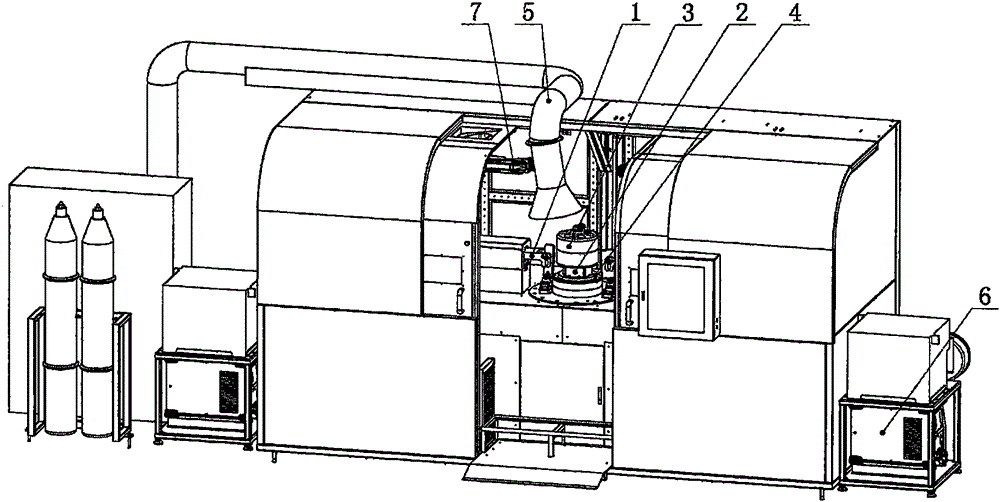
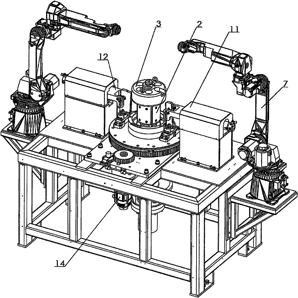
[0053] Such as figure 1 and figure 2 As shown, the automatic motor stator welding system is composed of a torsion angle assembly 1, an internal expansion assembly 2, a compression assembly 3, a loading and unloading lifting assembly 4, a shielding and dust removal system 5, a welding system 6 and a robot system 7;

[0054] The shielding and dust removal system 5 consists of two parts, the shielding room and the dust collector. The tooling parts such as the torsion angle assembly 1, the internal expansion assembly 2, the pressing assembly 3 and the loading and unloading lifting assembly 4 and the robot system 7 are arrange...


PUM


Abstract

The invention relates to an automatic motor stator welding system. The automatic motor stator welding system is composed of a torsional angle assembly (1), an inner expansion assembly (2), a pressing assembly (3), a feeding and discharging supporting assembly (4), a shielding and dust removing system (5), a welding system body (6) and a robot system (7). According to the core, a stator is driven through a servo motor, the stator torsional angle is achieved in cooperation with torsional angle blades on the two sides, an inner taper sleeve is downwards pulled through a hydraulic cylinder to expand multiple sections of expansion blocks to expand an inner hole of the stator tightly, a gland is pulled tightly through the hydraulic cylinder to press the stator, MIG is carried out to weld the stator through double robots at the same time, and the automatic motor stator welding system can adapt to welding of complex situations of the stator torsional angle and flanges.

Description


Claims


Application Information

Patent Timeline
Owner AMET WELDING AUTOMATION TECH BEIJING
Why Eureka
Try Eureka