Pressing plate type side guide centering device

A centering device and pressing plate technology, which is applied in auxiliary devices, auxiliary welding equipment, welding/cutting auxiliary equipment, etc., can solve the problems of inability to accurately control the centering thrust of side guides and easy damage to the edge of the strip, and achieve improved The accuracy and effectiveness of centering, and the effect of stabilizing welding efficiency and improving welding efficiency

Active Publication Date: 2016-02-03
BAOSHAN IRON & STEEL CO LTD
View PDF8 Cites 8 Cited by
  • Summary
  • Abstract
  • Description
  • Claims
  • Application Information

AI Technical Summary

Problems solved by technology

[0003] The technical problem to be solved by the present invention is to provide a pressing plate type side guide centering device. The centering device is provided with a moving pressing plate mechanism, which presses the upper surface of the strip steel through the moving pressing plate mechanism during the centering process of the strip being pushed by the side guide plate. , avoiding the arching deformation of the strip steel, overcoming the problem that the original side guide centering cannot accurately control the centering thrust of the side guide when producing thin strip steel, resulting in easy damage to the edge of the strip steel, and improving and stabilizing the welding of the welding machine Efficiency, which ultimately improves the reliability of unit operation

Method used


Image

  • Pressing plate type side guide centering device
  • Pressing plate type side guide centering device
  • Pressing plate type side guide centering device

Examples


Embodiment 1

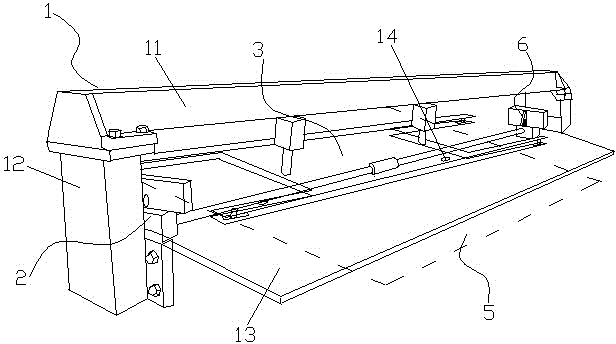
[0020] Such as figure 1 As shown, a pressure plate type side guide centering device includes a supporting frame structure 1 and a centering drive mechanism 2, and the centering drive mechanism 2 pushes the side edge of the strip steel 5 to be centered on the supporting surface of the supporting frame structure 1 , the support frame structure 1 is also provided with a mobile platen mechanism 3, the support frame structure 1 used in the embodiment of the present invention includes an upper support frame 11, a lower load-bearing frame 12 and a plane guide frame 13, and the plane guide frame 13 As a guide surface, a pair of limit position detection switches 14 are arranged on the plane guide frame 13 , the drive device 33 is installed on the upper support frame 11 , and the centering drive mechanism 2 is installed on the lower load-bearing frame 12 .

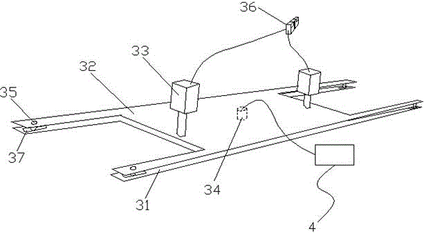
[0021] Such as figure 2 As shown, the moving platen mechanism 3 includes a lower laminate 31, an upper support plate 32 and a dr...


PUM


Abstract

The invention relates to the field of centering mechanisms of cold rolling finished product machine set welding machines, in particular to a side guide centering device. According to the pressing plate type side guide centering device, a movable pressing plate mechanism comprises a lower layer pressing plate, an upper layer support plate and a drive device. The edges of the lower layer pressing plate and the upper layer support plate are supported and connected through connection rods. The parts where the connection rods make contact with the lower layer pressing plate and / or the upper layer support plate are provided with slide grooves. The connection rods slide in the slide grooves freely. A deformation sensor is arranged in the middle between the lower layer pressing plate and the upper layer support plate. The lower layer pressing plate and the upper layer support plate are driven by the drive device to move synchronously to press strip steel. A controller controls and is connected with a stepping motor and the deformation sensor which are in a centering drive mechanism. According to the pressing plate type side guide centering device, the strip steel is prevented from humping deformation, and when the strip steel humps, a side guide plate can be controlled to stop running through a signal of the deformation sensor, so that the centering accuracy and effectiveness in the process in which thin strip steel is centered through the centering device are effectively improved, and the welding efficiency of the welding machines is improved and stabilized.

Description

technical field [0001] The invention relates to the field of centering mechanisms of welding machines for cold-rolled product units, in particular to a side guide centering device. Background technique [0002] The welding machine of the cold-rolled finished product unit adopts a high-current narrow lap welding machine. In order to ensure the flatness of the strip steel on both sides of the welding, a centering device is installed on the inlet side and the outlet side of the welding machine. The commonly used centering devices are mainly Camera centering device and side guide centering device, the camera centering device is suitable for thin strip steel and the side guide centering device is suitable for thick strip steel, the camera centering control is complicated and the equipment is expensive and the reliability is low, the corresponding side guide The centering control is simple, the equipment is cheap and the reliability is high, so some welding machines of cold-rolled...

Claims


Application Information

Patent Timeline
Patent Type & Authority Applications(China)
IPC IPC(8): B23K37/00
Inventor 陈杰张博林钱高展
Owner BAOSHAN IRON & STEEL CO LTD
Why Eureka
Try Eureka