Special tool for processing end surface of bearing cover

A technology of end face and tooling, which is applied in the direction of supports, metal processing equipment, metal processing machinery parts, etc., can solve the problems that the support cover cannot meet the drawing requirements, is easily affected by the quality of the blank, and has low repeat positioning accuracy, so as to avoid repetition The effect of positioning error, saving tooling adjustment time, and saving loading and unloading time

Active Publication Date: 2016-02-03
ANHUI HELI CO LTD
View PDF7 Cites 5 Cited by
  • Summary
  • Abstract
  • Description
  • Claims
  • Application Information

AI Technical Summary

Problems solved by technology

Because the milling of the upper and lower end faces of the support cover is used as the positioning reference plane for the subsequent process, if there is an error in the end face after milling, it will cause the hole drilled in the drilling process to be deflected by about 2 mm; There will be a deflection of the hole, which will cause one side of the Haval hole to be larger and one side to be smaller, and the difference range is 0.2-0.4, which will eventually cause the support cover to fail to meet the requirements of the drawing
[0004] In addition, the processing tooling used in this milling process requires two sets of molds to work alternately, which is cumbersome, labor-intensive, and low in production efficiency; and the support cover needs to be clamped twice, with low repeat positioning accuracy and prone to processing errors; The positioning of the bottom plane, the accuracy is poor, and it is easily affected by the quality of the blank

Method used


Image

  • Special tool for processing end surface of bearing cover
  • Special tool for processing end surface of bearing cover
  • Special tool for processing end surface of bearing cover

Examples


Embodiment Construction

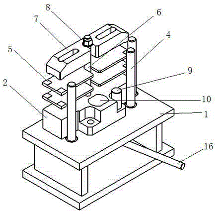
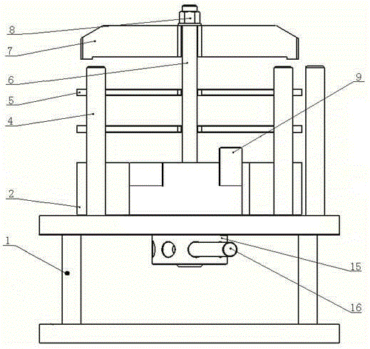
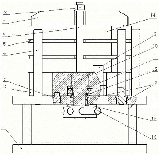
[0036] Such as figure 1 , 2 , 3, a special tool for processing the end face of the support cover, including a mold base 1, the upper end surface of the mold base 1 is connected to the rotary module 2 through a pin shaft 10, and the bottom of the pin shaft 10 located inside the rotary module 2 Plane bearings 11 and butterfly springs 12 are sheathed in turn on the outer periphery of the end; the bottom end of the pin shaft 10 passes through the mold base 1 and is connected with the lock nut 15; the rotating module 2 rotates on the mold base 1 around the pin shaft 10 , and positioning with the mold base 1 through the positioning pin 9; the upper end of the rotary module 2 is connected with a central stud 6, and the central stud 6 is movable with a backing plate 5 and a pressure plate 7, and the top of the central stud 6 A shoulder nut 8 is provided; a positioning column 4 for positioning the outer wall of the rotary module 2 is clamped on the mold base 1 located outside the rota...


PUM


Abstract

The invention provides a special tool for processing the end surface of a bearing cover. The special tool comprises a die holder, wherein the upper end surface of the die holder is connected with a rotating module, and the periphery of the bottom end of a pin shaft positioned in the rotating module is orderly sleeved with a plane bearing and a belleville spring; the bottom end of the pin shaft penetrates through the die holder to be connected with a locknut; the rotating module rotates round the pin shaft on the die holder and is positioned with the die holder through a positioning bolt; the upper end of the rotating module is connected with a central stud, the central stud is movably sleeved with a backing plate and a pressing plate, and a flanged nut is arranged at the top end of the central stud; a positioning column used for positioning the outer wall of the rotating module is clamped on the die holder positioned outside the rotating module. The special tool adopts the 180 degrees of rotation of the rotating module to meet the processing of the two parallel surfaces of the bearing cover, therefore realizing the purpose that one-time clamping meets the processing of two working procedures, greatly improving the processing efficiency and precision, and avoiding a repetitive position error.

Description

technical field [0001] The invention belongs to the field of mechanical processing, and in particular relates to a special tool for processing the end face of a support cover. Background technique [0002] The support cover is the upper Haval cover of the frame support used to install the drive axle on the forklift. The support cover and the frame support are both semicircular in shape. First, the drive axle is fixed on the frame support by screws, and then the assembly support Cover, the support cover and the vehicle frame support just form a full circle and embrace the axle journal of the drive axle. [0003] At present, the milling of the upper and lower end faces of the support cover is performed on a horizontal boring machine. It needs to process one side on a pair of molds first, then turn around and clamp the other side on the second pair of tooling, and then process the other side. Operation errors and irregularities of casting blanks, such as surface unevenness, ...

Claims


Application Information

Patent Timeline
Patent Type & Authority Applications(China)
IPC IPC(8): B23Q3/06
CPCB23Q3/062
Inventor 刘斌程贵珠邱林
Owner ANHUI HELI CO LTD
Why Eureka
Try Eureka