Feeding device

A technology of feeding device and feeding trolley, which is applied to the attachment device of sawing machine, metal processing, metal sawing equipment and other directions, can solve the problems of increased cost, high failure rate of feeding device, not economical and practical, etc., and achieves low cost and simple structure. Effect

Inactive Publication Date: 2016-02-03
天津市兴南电机制造有限公司
View PDF0 Cites 39 Cited by
  • Summary
  • Abstract
  • Description
  • Claims
  • Application Information

AI Technical Summary

Problems solved by technology

Some of the existing technologies use manual feeding, which is time-consuming and labor-intensive, and some rely on mechanical equipment to feed. Although this method saves manpower, it increases the cost of the equipment itself from another point of view, and the feeding of complex structures The failure rate of the device is high, not economical and practical

Method used


Image

  • Feeding device
  • Feeding device

Examples


Embodiment Construction

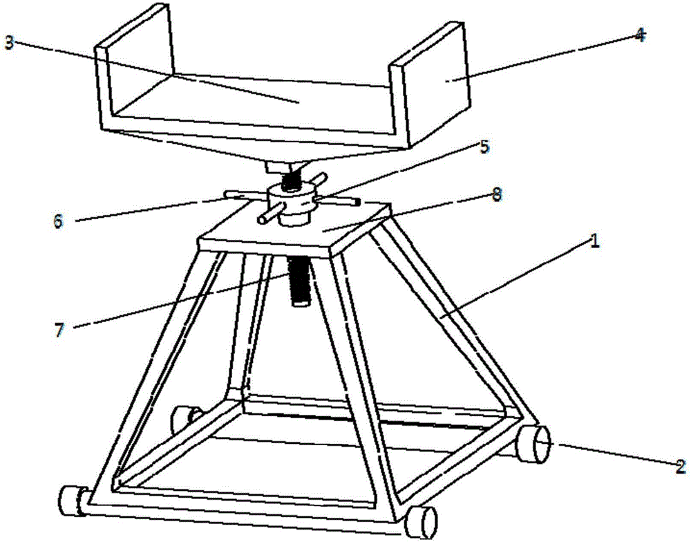
[0013] As shown in the figure, a feeding device includes a feeding trolley and a lock frame. The trolley includes a frame 1 and a tray 3. The frame 1 includes a top plate 8, a screw 7 and a screw nut 5. The top plate 8 has a hole, and the screw nut 5 The bearing is fixed on the position of the hole on the upper surface of the top plate 8, the screw nut 5 is coaxial with the hole, the screw nut 5 is sleeved on the lead screw 7, and the lower end of the lead screw 7 extends out of the lower surface of the top plate 8 through the hole, and the screw nut 5 The upper end of bar 7 is fixed with the bottom of tray 3. The nut 5 has a plurality of handles 6 evenly distributed around its axis.

[0014] There are rollers 2 at the bottom of the vehicle frame 1 . Both sides of the tray 3 have side baffles 4 . The workpiece is mounted on the pallet 3, and one end of the workpiece is mounted on the head of the band sawing machine. Turn the handle 6 to move the lead screw 7 up and down to a...


PUM


Abstract

The invention provides a feeding device which comprises a feeding trolley and a locking part. The trolley comprises a frame and a tray. The frame comprises a top plate, a screw rod and a nut. A hole is formed in the top plate. The nut is fixed to the position of the upper hole in the upper surface of the top plate through a bearing. The nut and the hole share the same coaxial line. The nut is arranged on the screw rod in a sleeving manner. The lower end of the screw rod penetrates the hole and extends out of the lower surface of the top plate. The upper end of the screw rod is fixed to the bottom of the tray. The feeding device has the beneficial effects of being simple in structure, convenient to use and practical.

Description

technical field [0001] The invention relates to a feeding device. Background technique [0002] There are two types of band sawing machines: horizontal and vertical. During the cutting process, after each section of material is cut, the material section needs to be pushed forward to the cutting position for the next cutting. Some of the existing technologies use manual feeding, which is time-consuming and labor-intensive, and some rely on mechanical equipment to feed. Although this method saves manpower, it increases the cost of the equipment itself from another point of view, and the feeding of complex structures The failure rate of the device is high, which is not economical and practical. Contents of the invention [0003] The problem to be solved by the present invention is to provide a feeding device, which is simple in structure, convenient and practical, and low in cost. [0004] In order to solve the above-mentioned technical problems, the technical solution adop...

Claims


Application Information

Patent Timeline
Patent Type & Authority Applications(China)
IPC IPC(8): B23Q7/00B23D59/00
Inventor 段永成
Owner 天津市兴南电机制造有限公司
Why Eureka
Try Eureka