Eureka AIR delivers breakthrough ideas for toughest innovation challenges, trusted by R&D personnel around the world.

Polishing disk and cooling device thereof

A cooling device and polishing disc technology, which is applied to grinding tools and other directions, can solve the problem of uneven temperature distribution of the polishing disc, and achieve the effect of reducing the temperature and improving the uniformity of the temperature distribution.

Active Publication Date: 2016-02-03
ACM RES SHANGHAI
View PDF11 Cites 3 Cited by
  • Summary
  • Abstract
  • Description
  • Claims
  • Application Information

AI Technical Summary

Problems solved by technology

If only the overall temperature of the polishing disc is lowered, there will still be uneven temperature distribution of the polishing disc, that is, the temperature in the middle area within the radius from the center of the polishing disc to the outer edge of the polishing disc is always higher than the temperature in other areas

Method used


Image

  • Polishing disk and cooling device thereof
  • Polishing disk and cooling device thereof
  • Polishing disk and cooling device thereof

Examples


Embodiment Construction

[0027] In order to describe the technical content, structural features, goals and effects of the present invention in detail, the following will be described in detail in conjunction with the embodiments and drawings.

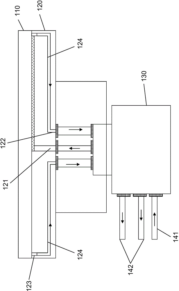
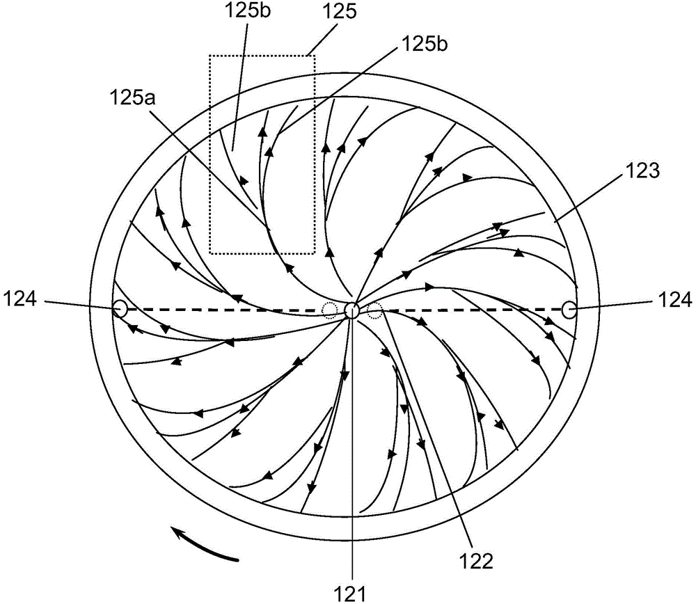
[0028] refer to figure 1 with figure 2 As shown, the structure of the polishing disc according to an embodiment of the present invention is disclosed. in figure 1 reveals a side-view structural diagram of the polishing disc, figure 2 A top-view structure diagram of the lower plate revealing the polishing plate, figure 2 The distribution of the cooling water grooves on the lower plate of the polishing disc is shown.

[0029] Such as figure 1 As shown, the polishing disc includes an upper disc 110 and a lower disc 120 . The top surface of the upper plate 110 is pasted with a polishing pad (not shown in the figure), the bottom surface of the upper plate 110 is docked with the top surface of the lower plate 120, and the upper plate 110 and the lower plate ...


PUM


Abstract

The invention discloses a cooling device of the polishing disk. The cooling device is applied to the polishing disk and comprises a cooling water inlet, cooling water outlets, an annular liquid return tank, liquid return channels and cooling water grooves. The cooling water inlet and the cooling water outlets are formed in the polishing disk. The annular liquid return tank and the liquid return channels are formed in the polishing disk, one end of each liquid return channel is communicated with the liquid return tank, and the other ends of the liquid return channels are communicated with the cooling water outlets. The cooling water grooves are formed in the polishing disk and located in the area, wrapped by the liquid return tank, of the polishing disk, and the cooling water grooves are evenly distributed in a branch shape. Each cooling water groove comprises a main groove body and side groove bodies, wherein one end of the main groove body is communicated with the cooling water inlet, the other end of the main groove body is communicated with the liquid return tank, one ends of the side groove bodies are communicated with the main groove body, and the other ends of the side groove bodies are communicated with the liquid return tank. The invention further discloses the polishing disk with the cooling device.

Description

technical field [0001] The invention relates to the technical field of chemical mechanical polishing, in particular to a polishing disc and a cooling device thereof. Background technique [0002] Chemical mechanical polishing (CMP) is a planarization technology that combines chemical corrosion and mechanical grinding. Its working principle is to place the workpiece to be polished in the polishing head, the polishing pad is pasted on the surface of the polishing disc, and the polished workpiece is treated by the polishing head. Apply a certain pressure to press the workpiece to be polished on the surface of the polishing pad, rely on the relative movement between the workpiece to be polished and the polishing pad, and realize the planarization of the workpiece to be polished by means of abrasive grains in the polishing liquid. During the polishing process, due to the friction between the workpiece to be polished and the polishing pad, a large amount of heat will be generated,...

Claims


Application Information

Patent Timeline
Patent Type & Authority Applications(China)
IPC IPC(8): B24B37/11
Inventor 杨贵璞王坚王晖
Owner ACM RES SHANGHAI
Why Eureka
Eureka Blog
Learn More