Sliding rail mechanism conducting automatic sliding and grinding

A sliding rail and automatic technology, which is applied in the direction of grinding frame, grinding bed, grinding slide plate, etc., can solve the problems of different structures and methods, complex structure design, impossibility of implementation, etc., to achieve easy popularization, convenient material selection, The effect of simple structure

Inactive Publication Date: 2016-02-03
倪煌斌
View PDF7 Cites 2 Cited by
  • Summary
  • Abstract
  • Description
  • Claims
  • Application Information

AI Technical Summary

Problems solved by technology

[0007] The above patent applications are all different due to their utility model purposes and technical problems to be solved, so their technical solutions include differences in structure and method, and they cannot be simply combined for this patent application, otherwise it will lead to structural design. Complicated, or impossible to implement, etc.

Method used


Image

  • Sliding rail mechanism conducting automatic sliding and grinding
  • Sliding rail mechanism conducting automatic sliding and grinding
  • Sliding rail mechanism conducting automatic sliding and grinding

Examples


Embodiment Construction

[0031] In order to make the purpose, technical solution and advantages of the present application clearer, the technical solution of the present application will be clearly and completely described below in conjunction with specific embodiments of the present application and corresponding drawings. Apparently, the described embodiments are only some of the embodiments of this application, not all of them. Based on the embodiments in this application, all other embodiments obtained by persons of ordinary skill in the art without making creative efforts belong to the scope of protection of this application.

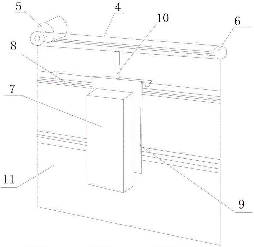
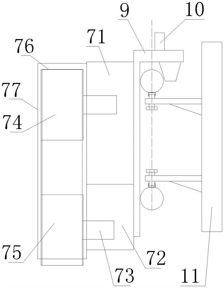
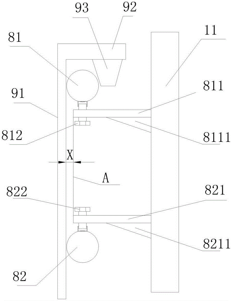
[0032] A sliding rail mechanism for automatic sliding grinding described in this application, the sliding rail mechanism includes a rear support plate 11, and a slide rail 8 is fixedly installed on the side wall of the rear support plate 11, and the slide rail 8 includes an upper sliding rail 81 And the lower rail 82, the upper slide rail 81 is clamped by the slide frame 9,...


PUM


Abstract

The invention discloses a sliding rail mechanism conducting automatic sliding and grinding. The sliding rail mechanism comprises a rear supporting plate 11. A sliding rail is fixedly installed on the side wall of the rear supporting plate 11. The sliding rail 8 comprises an upper sliding rail body 81 and a lower sliding rail body 82. A sliding frame 9 is clamped to the upper sliding rail body 81. The sliding frame 9 comprises a vertical frame 91 and a transverse frame 92 fixed to the upper end of the vertical frame 91. A clamping block 93 is downwards fixed to the transverse frame 92. The clamping block 93 is clamped to the upper sliding rail body 81. The side edge of the vertical frame 91 abuts against the side edge of the lower sliding rail body 82. A grinder 7 is fixedly installed on the sliding frame 9. A push handle 10 is fixedly installed on the transverse frame 92 of the top end of the sliding frame 9. An annular chain 4 is fixedly connected to the upper end of the push handle 10. The left end of the chain 4 is connected with a chain motor 5 in a sleeved manner, and the right end of the chain 4 is connected with a chain wheel 6 in a sleeved manner. At least suspension type automatic moving grinding is achieved, positioning is accurate, and an upper position and a lower position are accurately positioned for parallel automatic grinding.

Description

technical field [0001] The application relates to a sliding rail mechanism for automatic sliding grinding, which is used in vertical suspension transportation. Background technique [0002] In the prior art: [0003] For example: Chinese patent application number CN200680018506.9; application date 2006.05.23; the present invention relates to rail components for conveying suspended objects such as bottles or preforms. The component of the invention comprises two slide guides (11, 12) separated by a predetermined distance, said guide slides (11, 12) forming lateral support surfaces for objects conveyed along the conveying channel (13), e.g. Guide under the neck of the preform. The invention is characterized in that said track part defines a helically curved transfer section and comprises a frame (10) on which guides (11, 12) are arranged in a helical shape, at least one guide (11, 12 ) comprises a flat strap that can be removed from said frame (10). [0004] This appli...

Claims


Application Information

Patent Timeline
Patent Type & Authority Applications(China)
IPC IPC(8): B24B41/02
CPCB24B41/02
Inventor 倪煌斌
Owner 倪煌斌
Why Eureka
Try Eureka