

Pneumatic fixture
A technology of pneumatic clamps and cylinders, which is applied in the direction of chucks, manufacturing tools, manipulators, etc., can solve difficult problems such as various working environments, and achieve the effects of firm clamping, reduced surface contact stress, and easy realization
- Summary
- Abstract
- Description
- Claims
- Application Information
AI Technical Summary
Problems solved by technology
Method used
Image

Examples
Embodiment Construction
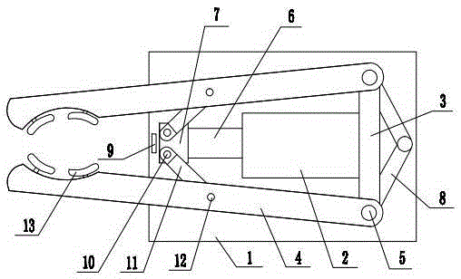
[0011] Below in conjunction with accompanying drawing, the present invention will be further described:
[0012] A pneumatic clamp comprises a bottom plate 1, on which a cylinder 2, a cylinder fixing plate 3 and two clamping rods 4 are arranged, and the two clamping rods 4 are symmetrically arranged on both sides of the cylinder 2, and one end of the clamping rod 4 is The fixed end, the other end of the clamping rod is the clamping end; the cylinder 2 is fixed on the cylinder fixing plate 3, and a push block 7 is arranged at the end of the push rod 6 of the cylinder, and there are two symmetrically arranged on the push block 7 which are movably connected with the push block. Connecting rod 11, connecting rod and push block can be connected by pin 10, and the other end of connecting rod 11 is connected on the described clamping rod 4 by pin shaft 12; It is installed on the bottom plate through, and the fixed end of the holding rod is movably connected to the connecting shaft 5....
PUM
 Abstract
Description
Claims
Application Information