
Vertical take-off and landing aircraft

A vertical take-off and landing, aircraft technology, applied in the field of aircraft, can solve the problems of increasing the difficulty of manufacturing, complex mechanical parts, increasing the cost of production and maintenance, etc., and achieve the effect of simplifying the mechanical structure and stabilizing the attitude control

Inactive Publication Date: 2016-02-03
吴建伟
View PDF0 Cites 12 Cited by
  • Summary
  • Abstract
  • Description
  • Claims
  • Application Information

AI Technical Summary

Problems solved by technology

Because the attitude control device used for vertical take-off and landing jet aircraft also uses complex mechanical parts, especially the rotatable nozzle, which not only requires high materials for making, but also is difficult to produce, so the cost of production and maintenance is increased; and This type of attitude control device is only applicable to aircraft that use vectoring nozzles or lift engines or even lift fans connected to engine power through transmissions as vertical thrust devices. Such aircraft use special vector engines
[0006] The above-mentioned types of vertical take-off and landing aircraft are used as attitude control devices with complex mechanical structures. A large number of mechanical parts not only increase the difficulty of manufacturing, but also increase the cost of production and maintenance; and the thrust device adopted by the aircraft type is restricted

Method used


Image

  • Vertical take-off and landing aircraft
  • Vertical take-off and landing aircraft
  • Vertical take-off and landing aircraft

Examples


Embodiment Construction

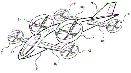
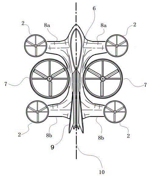
[0026] figure 2 Shown is a schematic diagram of an embodiment of a vertical take-off and landing aircraft of the present invention, including a fuselage 6, a main thrust device 7 and an attitude control device.

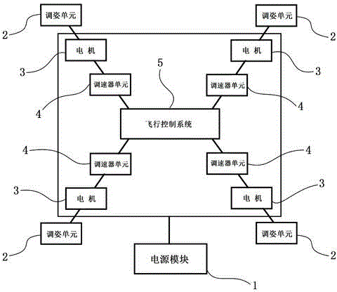
[0027] Depend on figure 1 As can be seen from the working principle diagram of the attitude control device of the vertical take-off and landing aircraft of the present invention, the attitude control device uses electric energy and is composed of a power supply module 1, an attitude adjustment unit 2, a motor 3, a governor unit 4, and a flight control system 5; the power supply module 1 provides power for the attitude control device; the attitude adjustment unit 2 is a fan blade connected to the power of the motor 3, and each attitude adjustment unit 2 is connected to a corresponding motor 3; the governor unit 4 is electrically connected to the motor 3 connected to adjust the output power of each motor 3 respectively, the governor unit 4 accepts the control of the f...


PUM


Abstract

The invention relates to a vertical take-off and landing aircraft with an attitude controller. The aircraft consists of a fuselage (6), two main thrust devices (7) which provide main thrust for the aircraft, and the attitude controller, wherein the attitude controller comprises a power module, attitude adjusting units (2), motors, speed regulator units and a flight control system; the aircraft adopts a double-main-wing structure, wherein the attitude adjusting units are separately connected to the left end of the first main wing (8a), the right end of the first main wing (8a), the left end of the second main wing (8b), and the right end of the second main wing (8b); the attitude adjusting units are ducted fans; the two main thrust devices are separately connected to the left side and the right side of the middle segment of the fuselage in a symmetrical manner, and the ducted fans are adopted; the air outlet of each duct is provided with a control surface; the main thrust device and the attitude adjusting units tilt towards the front of the aircraft; therefore, conventional complex mechanical components can be omitted, and the mechanical structure of the aircraft is simplified; the attitude controller and the main thrust devices are separated, so that the type of an engine adopted by the aircraft, and the types of thrust devices adopted by the aircraft, are not limited.

Description

technical field [0001] The invention relates to an aircraft, in particular to a vertical take-off and landing aircraft with an attitude control device. Background technique [0002] At present, the common vertical take-off and landing aircrafts include helicopters, tilt-rotor aircraft and vertical take-off and landing jet aircrafts. Vertical take-off and landing aircrafts need to rely on the attitude control device to maintain the balance of the aircraft when realizing vertical take-off and landing, and need to rely on the attitude control device to maintain the balance of the aircraft. Realize the control of the flight attitude of the aircraft in level, roll, pitch, and yaw, and realize the vertical take-off and landing, vertical and horizontal flight of the aircraft; the attitude control device refers to the device that controls the flight attitude of the aircraft. [0003] Conventional helicopters are fitted with autotilts, which consist of two main parts: a non-rotating ...

Claims


Application Information

Patent Timeline
IPC IPC(8): B64C13/00B64C27/02B64C27/32B64C27/52
CPCB64C29/00
Inventor 吴建伟
Owner 吴建伟
Features
  • Generate Ideas
  • Intellectual Property
  • Life Sciences
  • Materials
  • Tech Scout
  • Unparalleled Data Quality
  • Higher Quality Content
  • 60% Fewer Hallucinations
Learn More